 | –≠–ª–µ–∫—Ç—Ä–æ–Ω–Ω—ã–π –∫–æ–º–ø–æ–Ω–µ–Ω—Ç: FMC | –°–∫–∞—á–∞—Ç—å:  PDF PDF  ZIP ZIP |

MODEL
B3-13
DESCRIPTION
The FMC-461TM EMI filter has been specifically designed to reduce
the input line reflected ripple current of Interpoint's MHF, MTR, MTO,
MHV, MHF+, MHD, MTW, MHE, and MLP series of DC/DC
converters. It is intended for use in applications which have high
frequency switch-mode DC/DC converters and which must meet
MIL-STD-461C levels of conducted and radiated noise.
The FMC filter is built using thick-film hybrid technology and is
hermetically sealed in metal packages for military, aerospace, and
other high-reliability applications. The filter uses only ceramic
capacitors for reliable high temperature operation.
MIL-STD N
OISE
M
ANAGEMENT
When used in conjunction with Interpoint converters, the FMC-461
filter reduces input ripple current by 40 dB within the frequency band
of 200 kHz to 50 MHz. This gives the filter/converter combination a
performance which exceeds the CEO3 test of MIL-STD-461C.
Typical FMC-461 filter frequency response and output impedance
behavior are shown in Figures 4 and 5. CEO3 performance of a
typical converter with the FMC-461 filter connected is shown in
Figure 3.
T
RANSIENT
S
UPPRESSION
The FMC-461 filter also features a fast-reacting (1 pico second)
transient suppressor which begins clamping the input voltage at
approximately 47 VDC, protecting the DC/DC converter from
damage from induced line transients.
O
PERATING
T
EMPERATURE
The filter is rated to operate with no degradation of performance
over the temperature range of -55∞C to +125∞C (as measured at the
baseplate). Above +125∞C, current must be derated as specified on
the following page.
I
NSERTION
L
OSS
The maximum DC insertion loss for the FMC-461 filter (at a load of
22 watts) represents a power loss of less than 2% at typical input
voltage.
L
AYOUT
R
EQUIREMENT
The case pin, and ideally the case, should be tied to the case of the
converter through a low-inductance connection.
EMI I
NPUT
F
ILTER
28 V
OLT
I
NPUT
FMC EMI FILTER
2.7 AMP
F
EATURES
∑ ≠55∞C to +125∞C operation
∑ Up to 50 dB attenuation
400 kHz to 50 MHz
∑ Transient suppression
∑ Compliant to
MIL-STD-461C, CE03
∑ Compatible with
MIL-STD-704E
DC power bus
Size (max): Non-flanged, case H1
2.125 x 1.125 x 0.400 (53.98 x 28.58 x 10.16 mm)
Flanged, case K2
2.910 x 1.125 x 0.400 inches (73.91 x 28.58 x 10.16 mm)
See Section B8, cases H1 and K2, for dimensions.
Weight:
48 grams maximum
Screening: Standard, ES, or 883 (Class H). See Section C2 for
screening options, see Section A5 for ordering information.
FMC-461
FMC-461NT
2.7 Amp
2.7 Amp

TYPICAL CHARACTERISTICS
RECOMMENDED OPERATING CONDITIONS
ABSOLUTE MAXIMUM RATINGS
Input Voltage
∑ 0 to 40 VDC continuous
Lead Soldering Temperature (10 sec per lead)
∑ 300∞C
Storage Temperature Range (Case)
∑ ≠65∞C to +150∞C
B3-14
FMC EMI FILTER
2.7 AMP
Input Voltage Range
∑ 16 to 40 VDC continuous for 40 W load
Case Operating Temperature (Tc)
∑ ≠55∞C to +125∞C full power
Derating
∑ DC input and output current
Derate linearly from 100% at 125∞C to 0%
at 135∞C case
Electrical Characteristics: 25∞C Tc, nominal Vin, unless otherwise specified.
EMI I
NPUT
F
ILTERS
Capacitance
∑ 0.038 µF max, any pin to case
Isolation
∑ 100 megohm minimum at 500 V
∑ Any pin to case, except case pin
FMC-461
FMC-461NT
1
PARAMETER
CONDITIONS
MIN TYP MAX
MIN TYP MAX
UNITS
INPUT VOLTAGE
CONTINUOUS
0
28
40
0
28
40
VDC
INPUT CLAMPING
≠55∞C
40.8
45.1
49.4
--
--
--
VOLTAGE
25∞C
44.7
47.0
49.4
--
--
--
VDC
125∞C
44.7
49.5
54.2
--
--
--
INPUT CURRENT
--
--
2.7
--
--
2.7
A
DIFFERENTIAL MODE
200 kHz
40
--
--
40
--
--
dB
NOISE REJECTION
400 kHz - 50 MHz
50
--
--
50
--
--
COMMON MODE
NOISE REJECTION
2 MHz - 50 MHz
40
--
--
40
--
--
dB
DC RESISTANCE (R
DC
)
TC = 25∞C
--
--
0.20
--
--
0.20
OUTPUT VOLTAGE
2
STEADY STATE
V
OUT
= V
IN
- I
IN
(R
DC
)
V
OUT
= V
IN
- I
IN
(R
DC
)
VDC
OUTPUT CURRENT
RIPPLE
--
--
1.0
--
--
1.0
A rms
STEADY STATE
--
--
2.7
--
--
2.7
A
INTERNAL POWER
DISSIPATION
MAXIMUM CURRENT
--
--
1.6
--
--
1.6
W
Notes
1. The FMC-461NT does not have a transorb and does not clamp the input voltage
2. Typical applications result in Vout within 2% of Vin.
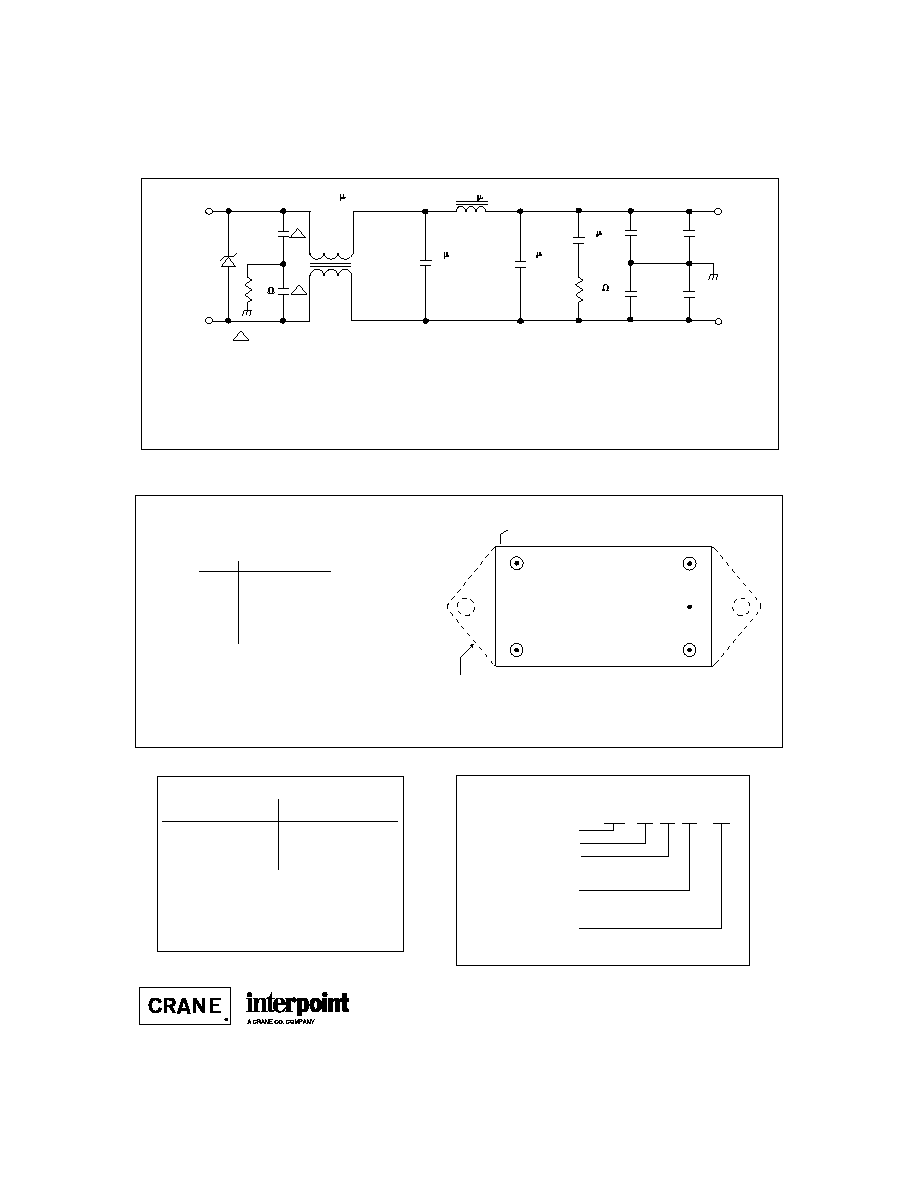
PIN OUT
MODEL NUMBERING KEY
1
2
3
4
5
Dot on top of package indicates pin one
Dotted line outlines flanged package option.
BOTTOM VIEW
FMC
NON-FLANGED AND FLANGED
FMC - 461 NT F / 883
Base Model
MIL-STD-461 Reference
Screening
(Standard screening has no designator
in this position.)
No Transorb Option
(Standard FMC-461 has no designator
in this position)
Case Option
(Non-flanged case has no designator in
this position)
B3-15
EMI I
NPUT
F
ILTERS
See Section B8, cases H1 and K2 for dimensions.
Pin
Designation
1
Positive Input
2
Positive Output
3
Case Ground
4
Output Common
5
Input Common
F
IGURE
2: P
IN
O
UT
DSCC NUMBER
DSCC D
RAWING
(5915)
94010-01HXC
94010-01HZC
94010-02HXC
1
94010-02HZC
1
FMC-461 F
ILTER
S
IMILAR
P
ART
FMC-461/883
FMC-461F/883
FMC-461NT/883
1
FMC-461NTF/883
1
For exact specifications for a DSCC product, refer to the
DSCC drawing. See Section A3, "SMD/DSCC Lists", for
more information.
6 F
6800 pF / 500 V
(4 times)
Positive
Input
Input
Common
Positive
Output
Output
Common
FMC-461
FMC-461/883
35.6 H
1 F
68
3300 pF / 500 V
IN5649A
277 H
6 F
4.7
1
1
1
F
IGURE
1: S
CHEMATIC
≠ T
YPICAL
V
ALUES
FMC EMI FILTER
2.7 AMP
1. No transorb (NT)
Flanged SMDs have the suffix HZC instead of HXC.
The case ground connection between the filter and the converter should be as low an impedance as possible
to minimize EMI. Direct contact of baseplate to chassis ground provides the lowest impedance.

B3-16
Typical Performance Curves: 25∞C Tc , nominal Vin, unless otherwise specified.
EMI I
NPUT
F
ILTERS
FMC EMI FILTER
2.7 AMP
90
70
50
30
.015
0.1
1
10
50
10
EMISSION LEVEL (dmA)
FREQUENCY (MHz)
F
IGURE
3
FREQUENCY (Hz)
1 K
Attenuation (dB)
10 K
100 K
1 M
-95
-75
-55
-35
-15
5
F
IGURE
4
F
IGURE
5
-10
0
10
FREQUENCY (Hz)
1 K
10 K
100 K
1 M
-20
dB Ohms = 20 log Z
out
DC/DC Converter Typical Worst Case
EMI With FMC-461 Filter
FMC-461 Typical Amplitude
Response vs. Frequency
Typical Output Impedance (Z)
With Input Shorted
25621-001-DTS Rev A
DQ# 4003
All technical information is believed to be accurate, but no responsibility is
assumed for errors or omissions. Interpoint reserves the right to make changes in
products or specifications without notice. FMC-461 is a trademark of Interpoint.
Copyright © 1991 - 1999 Interpoint. All rights reserved.

B8-17
CASE H
C
ASES
CASE H
BOTTOM VIEW
See Figures 29 ≠ 34
for pin configurations.
2.125 max
(53.98)
1.125 max
(28.58)
Materials
Header Cold Rolled Steel/Nickel/Gold
cases H1 and H2
Cold Rolled Steel/Nickel/Tin
cases H3, H4, and H5
Cover Kovar/Nickel
cases H1 and H2
Cold Rolled Steel/Nickel/Tin
cases H3, H4, and H5
Pins #52
alloy
ceramic seal
case H1
case H2 (except MHV Series Single and Dual)
compression glass seal
MHV Series Single and Dual
case H3, H4, H5
Case dimensions in inches (mm)
Tolerance
±
0.005 (0.13) for three decimal places
±
0.01 (0.3) for two decimal places
unless otherwise specified
CAUTION
Heat from reflow or wave soldering may damage
the device. Solder pins individually with heat
application not exceeding 300
∞
C for 10 seconds
per pin.
Dot on top of case indicates pin one
0.155 (3.94)
0.955 (24.26)
Seam Seal
0.000
0.040 dia
(1.02)
0.000
0.000
0.400 max.
(10.16)
0.25
±
0.03
(6.4
±
0.8)
0.555 (14.1)
0.245
(6.22)
1.845
(46.86)
2.090
(53.01)
1.110 (28.19)
1
2
3
4
5
FMC EMI Filter: Screening ≠ Standard, ES, or 883
SFMC EMI Filter: Screening ≠ Space Standard, H, or K
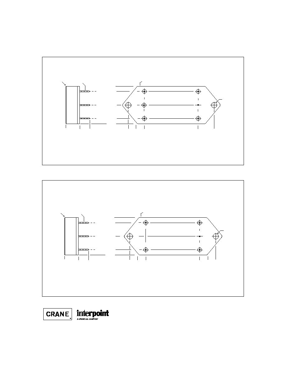
BOTTOM VIEW CASE H1
Squared corner and dot on top
of case indicate pin one.
F
IGURE
29: C
ASE
H1
F
IGURE
28: C
ASE
H M
AXIMUM
D
IMENSIONS
Note: Although every effort has been made to render the case drawings at actual size, variations in the printing process may cause some distortion. Please refer
to the numerical dimensions for accuracy.

B8-26
CASE K
C
ASES
Materials
Header Case K1 - K3
Cold Rolled Steel/Nickel/Gold
Cases K4 - K8
Cold Rolled Steel/Nickel/Tin
Cover
Case K1 - K3
Kovar/Nickel
Case K4 - K8
Cold Rolled Steel/Nickel/Tin
Pins
#52 alloy (all cases)
Case K1, K2, and K3 (except MHV Series Single and Dual)
ceramic seal
Cases K4 - K8 and MHV Series Single and Dual (K3)
compression glass seal
Case dimensions in inches (mm)
Tolerance
±
0.005 (0.13) for three decimal places
±
0.01 (0.2) for two decimal places
unless otherwise specified
CASE K
BOTTOM VIEW
See Figures 42 - 48
for pin configuration
CAUTION
Heat from reflow or wave soldering may damage
the device. Solder pins individually with heat
application not exceeding 300
∞
C for 10 seconds
per pin.
Flange Thickness:
Cases K1, K2, K3 and MLP Series (K5)
0.060 (1.52)
Cases K4, K5 (except MLP Series), K6, K7, and K8
0.067 +0.005/-0.007 (1.70 +0.13/-0.8)
1.125 max
(28.58)
2.910 max
(73.91)
Dot on top of case indicates pin one
F
IGURE
41: C
ASE
K M
AXIMUM
D
IMENSIONS
B8-27
CASE K
C
ASES
0.155 (3.94)
0.955 (24.26)
0.000
0.040 dia
(1.02)
0.000
0.000
0.400 max.
(10.16)
0.25
±
0.03
(6.4
±
0.8)
0.555 (14.1)
0.245
(6.22)
1.845
(46.86)
1.110 (28.19)
1
2
4
5
Flanged case
FM-704A EMI Filter: Screening ≠ Standard, ES, or 883
BOTTOM VIEW CASE K1
0.162 dia
(4.11)
Seam Seal
0.230
(5.84)
2.320
(58.93)
Dot on top of case indicates pin one
3
6
F
IGURE
42: C
ASE
K1
0.155 (3.94)
0.955 (24.26)
Seam Seal
0.000
0.040 dia
(1.02)
0.000
0.000
0.400 max.
(10.16)
0.25
±
0.03
(6.4
±
0.8)
0.555 (14.1)
0.245
(6.22)
1.845
(46.86)
2.090
(53.01)
1.110 (28.19)
1
2
4
5
Flanged cases: Designator required in Case Option position of model number.
FMC EMI Filter: Screening ≠ Standard, ES, or 883
SFMC EMI Filter: Screening ≠ Space Standard, H, or K
BOTTOM VIEW CASE K2
0.162 dia
(4.11)
0.230
(5.84)
2.320
(58.93)
Dot on top of case indicates pin one
3
F
IGURE
43: C
ASE
K2

C2-10
TEST (125∞C Products)
STANDARD
/ES
/883 (Class H)*
PRE-CAP INSPECTION
Method 2017, 2032
yes
yes
yes
TEMPERATURE CYCLE (10 times)
Method 1010, Cond. C, -65∞C to 150∞C
no
no
yes
Method 1010, Cond. B, -55∞C to 125∞C
no
yes
no
CONSTANT ACCELERATION
Method 2001, 3000 g
no
no
yes
Method 2001, 500 g
no
yes
no
BURN-IN
Method 1015, 160 hours at 125∞C
no
no
yes
96 hours at 125∞C case (typical)
no
yes
no
FINAL ELECTRICAL TEST MIL-PRF-38534, Group A
Subgroups 1 through 6: -55∞C, +25∞C, +125∞C
no
no
yes
Subgroups 1 and 4: +25∞C case
yes
yes
no
HERMETICITY TESTING
Fine Leak, Method 1014, Cond. A
no
yes
yes
Gross Leak, Method 1014, Cond. C
no
yes
yes
Gross Leak, Dip (1 x 10
-3
)
yes
no
no
FINAL VISUAL INSPECTION
Method 2009
yes
yes
yes
Test methods are referenced to MIL-STD-883 as determined by MIL-PRF-38534.
*883 products are built with element evaluated components and are 100% tested and guaranteed over
the full military temperature range of ≠55∞C to +125∞C.
MOR Series
MFLHP Series
MFL Series
MHP Series
MTR Series
MQO Series**
MHD Series
MHV Series
MHF+ Series
MHF Series**
MGA Series
MSA Series
MGH Series
MCH Series
FM-704A EMI Filter
FMD**/FME EMI Filter
FMC EMI Filter
FMH EMI Filter
FMGA EMI Filter
FMSA EMI Filter
HUM Modules**
LCM Modules**
LIM Modules
QA SCREENING
125∞C PRODUCTS
125∞C P
RODUCTS
Applies to the following products
**MFLHP Series, MQO Series, MHF Series, FMD EMI Filters, Hum Modules, and LCM Modules do not offer
`883" screening.