
1
DESCRIPTION
The FMTR SeriesTM of DC/DC converters offers up to 30 watts of
output power from single or dual output configurations. They
operate over the full military temperature range with up to 83% effi-
ciency. FMTR converters are packaged in hermetically sealed metal
cases, making them ideal for use in military, aerospace and other
high reliability applications.
C
ONVERTER
D
ESIGN
The FMTR converters are constant frequency, pulse-width mod-
ulated switching regulators which use a quasi-square wave, single
ended, forward converter design. Tight load regulation is maintained
via wide bandwidth magnetic feedback and, on single output
models, through use of remote sense.
Indefinite short circuit protection and overload protection are
provided by a constant current-limit feature. This protective system
senses current in the converter's secondary stage and limits it to
approximately 115% of the maximum rated output current.
B
UILT
-
IN
F
ILTERS
The built-in input and output filters reduce layout issues and
conserve board space. The 2.7 amp EMI input filter meets MIL-STD-
461C, CE03 and allows filtering of additional converters through the
filter output pins. The output filter reduces high frequency common
and differential mode noise. It allows a higher bandwidth ripple
voltage measurement and eliminates the need for external output
decoupling capacitors. Both input and output filters reduce radiated
emissions providing quieter operation than conventional DC/DC
converters.
W
ARNING
: R
EQUIRED
D
AMPING
N
ETWORK
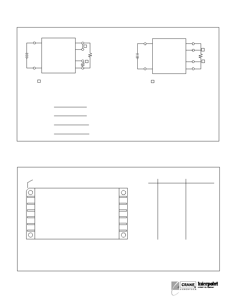
To prevent damage to the internal circuitry an external capacitor and
resistor are required across the filter outputs (pins 3 and 4) as
shown in Figure 1. This applies to both single and dual output
models. The recommended capacitor type is wet tantalum, MIL-C-
39006.
EMI F
ILTERED
DC/DC C
ONVERTERS
28 V
OLT
I
NPUT
FMTR SERIES
30 WATT
F
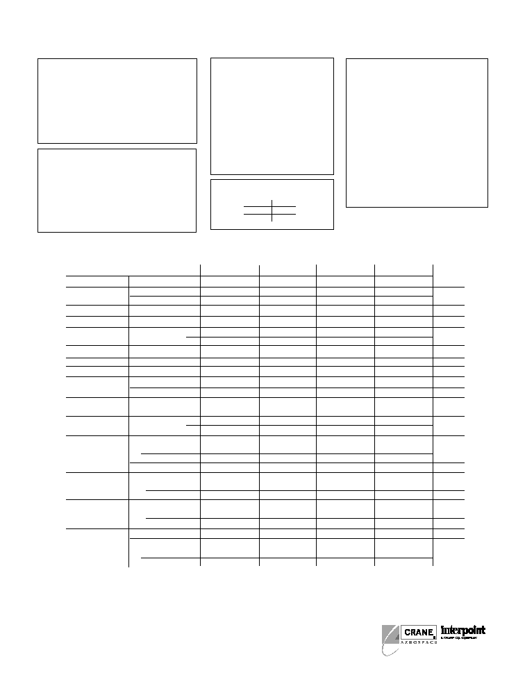
EATURES
� EMI input filter, up to
50 dB attenuation
� �55� to +125�C operation
� High frequency output filter
� 17 to 40 VDC input
� Fully isolated, magnetic feedback
� 600 kHz typical�Single Ended Forward
� Inhibit and synchronization functions
� Indefinite short circuit protection
� Trim and remote sense on singles
� Up to 83% efficiency
� Up to 50V for 50 ms transient
protection
MODELS
VDC O
UTPUT
SINGLE
3.3
5
12
15
DUAL
�5
�12
�15
Size (max): 3.005 x 1.505 x 0.400 inches (76.33 x 38.23 x 10.16 mm)
Weight:
100 grams maximum
Screening: Standard or ES, see the Environmental Screening table
11 Positive
Output
10 Output
Common
28 Vin 8
Input Common 7
Inhibit/Sync 2
Return
Inhibit 5
Sync 1
EMI Input Filter 2.7 A max.
Vin
Vout
+
�
+
+
�
�
+
�
DC/DC Converter
High Frequency
Output Filter
4 Filter Output
3 Filter Output Rtn
Additional
DC/DC
Converters
2.2
220
�F
Required
damping
network
Sync
Inhibit
~
+Vin
Rtn
Inh
Sync
Rtn
F
IGURE
1: FMTR T
YPICAL
I
NPUT
I
NTERFACE
A
PPLIES TO
S
INGLES AND
D
UALS
(S
HOWN WITH
S
INGLE
O
UTPUT
)
SINGLE OUTPUT MODELS
FMTR283R3S
FMTR2805S
FMTR2812S
FMTR2815S
PARAMETER
CONDITION
MIN
TYP
MAX
MIN TYP MAX
MIN
TYP
MAX
MIN
TYP
MAX
UNITS
OUTPUT VOLTAGE
25�C
3.26
3.30
3.34
4.95
5.00
5.05 11.88 12.00 12.12 14.85 15.00 15.15
VDC
�55�C TO +125�C
3.20
3.30
3.40
4.85
5.00
5.15 11.64 12.00 12.36 14.55 15.00 15.45
OUTPUT CURRENT
1
V
IN
= 17 to 40 VDC
0
��
6.06
0
--
5.0
0
--
2.5
0
--
2.0
A
OUTPUT POWER
1
V
IN
= 17 to 40 VDC
0
--
20
0
--
25
0
--
30
0
--
30
W
OUTPUT RIPPLE
10 kHz � 2 MHz
25�C
--
70
140
--
110
220
--
60
120
--
25
50
mV p-p
VOLTAGE
--
--
180
--
--
260
--
--
160
--
--
90
LINE REGULATION
2
V
IN
= 17 to 40 VDC
--
--
10
--
15
50
--
15
50
--
15
50
mV
LOAD REGULATION
NO LOAD TO FULL
--
--
10
--
15
50
--
15
50
--
15
50
mV
INPUT VOLTAGE
1
NO LOAD TO FULL
17
28
40
17
28
40
17
28
40
17
28
40
VDC
INPUT CURRENT
1
NO LOAD
--
30
75
--
35
75
--
35
75
--
35
75
mA
INHIBITED
--
7
8
--
3
8
--
3
8
--
3
8
mA
INPUT RIPPLE
CURRENT
10 kHz � 10 MHz
--
5
10
--
5
10
--
5
10
--
5
10
mA p-p
EFFICIENCY
INCLUDES FILTER
25�C
73
75
--
75
77
--
79
82
--
80
83
--
%
70
72
--
72
74
--
76
78
--
77
79
LOAD FAULT
3
POWER DISSIPATION
SHORT CIRCUIT 25�C
--
--
10
--
--
10
--
--
10
--
--
10
W
�55�C TO +125�C
--
--
12
--
--
12
--
--
12
--
--
12
RECOVERY
4, 6
--
1.4
6
--
1.4
5
--
1.4
5
--
1.4
5
ms
STEP LOAD RESP.
50% � 100% � 50%
TRANSIENT
--
�125
�250
--
�200 �300
--
�250 �400
--
�350 �500
mV pk
RECOVERY
4, 6
--
--
200
--
60
200
--
60
200
--
60
200
�s
STEP LINE RESP.
6
17 � 40 � 17 VDC
TRANSIENT
5
--
--
�300
--
�200 �300
--
�400 �500
--
�500 �600
mV pk
RECOVERY
4
--
--
300
--
--
300
--
--
300
--
--
300
�s
START-UP
1
DELAY
--
1.4
5
--
1.4
5
--
1.4
5
--
1.4
5
ms
OVERSHOOT
6
FULL LOAD
--
0
50
--
0
50
--
0
120
--
0
150
mV pk
NO LOAD
--
33
150
--
50
250
--
120
600
--
150
750
TYPICAL CHARACTERISTICS
SYNC AND INHIBIT
RECOMMENDED OPERATING CONDITIONS
ABSOLUTE MAXIMUM RATINGS
Input Voltage
� 17 to 40 VDC
Output Power
� 25 to 30 watts depending on model
� Input filter current, 2.7 A max.
Lead Soldering Temperature (10 sec per pin)
� 300�C
Storage Temperature Range (Case)
� �65�C to +135�C
2
FMTR SERIES
30 WATT
DC/DC C
ONVERTERS
Output Voltage Temperature Coefficient
� 100 ppm/�C typical
Input to Output Capacitance
� 50 pF typ
Current Limit
� 115% of full load typical
Isolation
� 100 megohm minimum at 500 V
Audio Rejection
� 40 dB typical
Conversion Frequency
� Free run 550 min, 600 typ, 650 max kHz
� External sync 500 to 675 kHz
Inhibit Pin Voltage (unit enabled)
� 9 to 11 V
Input Filter DC Resistance
� 0.2 ohms max
Input Voltage Range
� 17 to 40 VDC continuous
� 50V for 50 ms transient protection
Case Operating Temperature (Tc)
� �55�C to +125�C full power
� �55�C to +135�C absolute
Derating Output Power/Current
� Linearly from 100% at 125�C to 0% at 135�C
Electrical Characteristics: -55�C to +125� Tc, 28 VDC Vin, 100% load, free run, unless otherwise specified.
Sync (500 to 675 kHz)
� Duty cycle 40% min, 60% max
� Logic low 0.8 V max
� Logic high 4.5 V min, 5 V max
� Referenced to inh/sync return
� If not used, connect to inh/sync return
Inhibit TTL Open Collector
� Logic low (output disabled)
Voltage
0.8 V
Inhibit pin current 8.0 mA max
� Referenced to inh/sync return
� Logic high (output enabled)
Open collector
Notes
1. Tc = �55�C to +125�C
2. Operation is limited below 17V (see Figure 19).
3. Indefinite short circuit protection not guaranteed above 125�C case.
4. Recovery time is measured from application of the transient to point at which
Vout is within 1% of final value.
5. Transition time
10 �s.
6. Parameter shall be tested as part of device characterization and after design
and process changes. Thereafter, parameters shall be guaranteed to the
limits specified in the electrical Characteristics table.
EMI FILTER
Noise Rejection - Minimum
500 kHz
55 dB
1 MHz
60 dB
5 MHz
60 dB

DUAL OUTPUT MODELS
FMTR2805D
FMTR2812D
FMTR2815D
PARAMETER
CONDITIONS
MIN TYP MAX
MIN
TYP
MAX
MIN
TYP
MAX
UNITS
OUTPUT VOLTAGE
25�C
+V
OUT
4.95
5.00
5.05
11.88
12.00
12.12 14.85
15.00
15.15
�V
OUT
4.90
5.00
5.08
11.80
12.00
12.18
14.76
15.00
15.23
VDC
�55�C TO +125�C +V
OUT
4.85
5.00
5.15
11.64
12.00
12.36 14.55
15.00
15.45
�V
OUT
4.80
5.00
5.18
11.56
12.00
12.42
14.46
15.00
15.53
OUTPUT CURRENT
1, 2
V
IN
= 17 TO 40 VDC
0
2.5
4.5
0
1.25
2.25
0
1.0
1.8
A
OUTPUT POWER
1, 2
V
IN
= 17 TO 40 VDC
0
--
25
0
--
30
0
--
30
W
OUTPUT RIPPLE
10 kHz - 2 MHz
25�C
--
75
140
--
25
80
--
40
80
mV p-p
VOLTAGE +/� V
OUT
--
--
180
--
--
120
--
--
120
LINE REGULATION
+V
OUT
--
10
50
--
10
50
--
10
50
mV
V
IN
= 17 TO 40VDC
�V
OUT
--
50
100
--
50
150
--
50
180
LOAD REGULATION
+V
OUT
--
5
50
--
15
50
--
15
50
mV
NO LOAD TO FULL
�V
OUT
--
45
120
--
45
170
--
40
190
CROSS REGULATION
25�C SEE NOTES 4 & 9
--
8
--
--
5
--
--
3
--
%
EFFECT ON �V
OUT
25�C SEE NOTES 5 & 9
--
5
--
--
4
--
--
4
--
INPUT VOLTAGE
1
CONTINUOUS
17
28
40
17
28
40
17
28
40
VDC
NO LOAD TO FULL
TRANSIENT 50 ms
0
--
50
0
--
50
0
--
50
V
INPUT CURRENT
NO LOAD
--
35
75
--
50
75
--
50
75
mA
INHIBITED
--
3
8
--
3
8
--
3
8
mA
INPUT RIPPLE
CURRENT
1
10 kHz - 10 MHz
--
5
10
--
5
10
--
5
10
mA p-p
EFFICIENCY
25�C
75
77
--
78
80
--
79
82
--
%
72
74
--
75
77
--
76
78
--
LOAD FAULT
6
POWER DISSIPATION
SHORT CIRCUIT
25�C
--
--
10
--
--
10
--
--
10
W
--
--
12
--
--
12
--
--
12
RECOVERY
9
--
1.4
5.0
--
1.4
5.0
--
1.4
5.0
ms
STEP LOAD 50
� 100 � 50% BALANCED
RESPONSE � V
OUT
TRANSIENT
--
�200
�300
--
�150
�300
--
�200
�400
mV pk
RECOVERY
7, 9
--
100
200
--
100
200
--
100
200
�s
STEP LINE
9
17 � 40 � 17 V
IN
RESPONSE � V
OUT
TRANSIENT
8
--
�200
�400
--
�200
�400
--
�400
�500
mV pk
RECOVERY
7
--
--
300
--
--
300
--
--
300
�s
START�UP
1
DELAY
--
1.4
5
--
1.4
5
--
1.4
5
ms
OVERSHOOT
9
FULL LOAD
--
0
50
--
0
120
--
0
150
mV pk
NO LOAD
--
50
250
--
120
600
--
150
750
3
FMTR SERIES
30 WATT
DC/DC C
ONVERTERS
Electrical Characteristics: -55�C to +125�C Tc, 28 VDC Vin, 100% load, free run, unless otherwise specified.
Notes
1. Tc = �55�C to +125�C.
2. Up to 90% of the total output current/power is available from either output
providing the positive output is carrying at least 10% of the total output
power.
3. Operation is limited below 17 V (see Figure 19).
4. Effect on the negative output under the following conditions:
+P
out
20% to 80%; �P
out
80% to 20%
5. Effect on the negative output under the following conditions:
+P
out
50%; �P
out
10% to 50%
6. Indefinite short circuit protection not guaranteed above 125�C case.
7. Recovery time is measured from application of the transient to point at which
Vout is within 1% of final value.
8. Transition time
10 �s.
9. Parameter shall be tested as part of device characterization and after design
and process changes. Thereafter, parameters shall be guaranteed to the
limits specified in the electrical Characteristics table.
TRIM AND REMOTE SENSE (AVAILABLE ON SINGLE OUTPUT MODELS ONLY)
Trim Formulas
Vout = desired output voltage; Rt = trim resistor
3.3V: Rt = 1300 * Vout � 4304
1.2475
5V:
Rt = 1300 * Vout � 6512
1.2475
12V: Rt = 1300 * Vout � 15631
1.2475
15V: Rt = 1300 * Vout � 19498
1.2475
4
FMTR SERIES
30 WATT
DC/DC C
ONVERTERS
PIN OUT
RL
OUTPUT
COMMON
REMOTE SENSE CONNECTION
2 Make connections at load.
FMTR SINGLE OUTPUT CONVERTER
10
9
11
7
8
+VIN
INPUT
COMMON
12
SENSE
RETURN
SENSE
POSITIVE
OUTPUT
2
2
EXTERNAL TRIM CONNECTION
1 Make connections at converter.
RL
OUTPUT
COMMON
FMTR SINGLE OUTPUT CONVERTER
10
9
11
7
8
+VIN
INPUT
COMMON
12
SENSE
RETURN
SENSE
POSITIVE
OUTPUT
1
RT
1
F
IGURE
3: R
EMOTE
S
ENSE2, 3
F
IGURE
2: T
RIM
C
ONNECTION1, 2, 3
Notes for Remote Sense and Trim
1. When trimming output voltage and/or remote sensing, the total
output voltage increase must be less than 0.6 volts at the converters
pins to maintain specified performance.
2. If neither voltage trim nor remote sense will be used, connect pin 9
to pin 10 and pin 11 to pin 12 or the output voltage will increase by
1.2 volts
3. CAUTION: The converter will be permanently damaged if the posi-
tive remote sense (pin 12) is shorted to ground. Damage may also
result if the output common or positive output is disconnected from
the load with the remote sense leads connected to the load.
Pin
Single Output
Dual Output
1
Sync
Sync
2
Inhibit/Sync Rtn
Inhibit/Sync Rtn
3
Filter Out Rtn
Filter Out Rtn
4
Filter Out
Filter Out
5
Inhibit
Inhibit
6
No connection
No connection
7
Input Common
Input Common
8
28 V Input
28V Input
9
Sense Rtn
No connection
10
Output Common
Negative Output
11
Positive Output
Output Common
12
Positive Sense
Positive Output
F
IGURE
4: P
IN
O
UT
See page 7 for dimensions.
Angled corner indicates pin one.
1
2
3
4
5
6
12
11
10
9
8
7
TOP VIEW
FMTR
(Pin side, marked side)
5
FMTR SERIES
30 WATT
DC/DC C
ONVERTERS
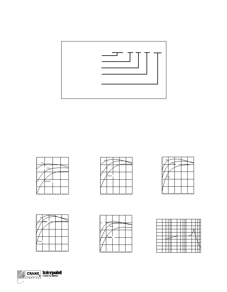
Typical Performance Curves: 25�C Tc, 28 VDC Vin, 100% load, free run, unless otherwise specified.
F
IGURE
8
F
IGURE
10
OUTPUT POWER (Watts)
FMTR2812D EFFICIENCY
E
F
F
IC
IE
N
C
Y
(
%)
60
85
80
75
70
65
5
10
15
20
16V
40V
28V
0
10
20
30
40
50
60
70
80
90
100
0.1
1
10
100
FREQUENCY (kHz)
AUDIO REJECTION, FMTR SERIES
ATTENUATION (dB)
OUTPUT POWER (Watts)
FMTR2805S EFFICIENCY
E
F
F
IC
IE
N
C
Y
(
%)
60
85
80
75
70
65
5
10
15
20
25
16V
40V
28V
F
IGURE
5
OUTPUT POWER (Watts)
FMTR2812S EFFICIENCY
E
F
F
IC
IE
N
C
Y
(
%)
60
85
80
75
70
65
5
16V
28V
40V
10
15
20
F
IGURE
6
OUTPUT POWER (Watts)
FMTR2815D EFFICIENCY
E
F
F
IC
IE
N
C
Y
(
%)
65
90
85
80
75
70
5
10
15
20
40V
28V
16V
F
IGURE
9
F
IGURE
7
OUTPUT POWER (Watts)
FMTR2815S EFFICIENCY
E
F
F
IC
IE
N
C
Y
(
%)
62
87
82
77
72
67
5
16V
28V
40V
10
15
20
25
MODEL NUMBERING KEY
FMTR 28 12 D / ES
Base Model
Input Voltage
Output Voltage
Number of Outputs
(S = single, D = dual)
Screening
(Standard screening has no designator
in this position.)