 | ÐлекÑÑоннÑй компоненÑ: HSH1205D | СкаÑаÑÑ:  PDF PDF  ZIP ZIP |
Äîêóìåíòàöèÿ è îïèñàíèÿ www.docs.chipfind.ru
1
®
MODELS
VDC O
UTPUT
DUAL
±5
DC/DC C
ONVERTERS
12 V
OLT
I
NPUT
HSH SERIES
1.5 WATT
F
EATURES
· -55°C to +150°C operation
· 6 to 20 VDC input voltage range
· Fully isolated
· Magnetic feedback
· Variable operating frequency
· Topology
Self Oscillating Flyback
· Inhibit function
DESCRIPTION
With a miniature footprint of just 0.8 square inches, the HSH
SeriesTM of DC/DC converters delivers 1.5 watts of output power
while saving significant board real estate. The wide input voltage
range of 6 to 20 VDC accepts the varying voltages of military, indus-
trial, or battery 15V bus power and tightly regulates output voltages
to protect downstream components. Transient protection of 40 volts
for up to 120 milliseconds.
C
ONVERTER
D
ESIGN
HSH Series DC/DC converters incorporate a flyback topology with a
variable frequency, nominally 370 kHz. Output voltage is magneti-
cally fed back to the input side of the PWM to regulate output volt-
age.
Up to 80% of the load may be on one output providing that the other
output carries a minimum of 20% of the total load. This dual model
can be used as a single output voltage by connecting the load
between positive and negative outputs, leaving the common uncon-
nected resulting in double the output voltage. (ex: HSH1205D can
be used as a 10 VDC output.)
I
NHIBIT
F
UNCTION
When an open collector TTL logic low is applied to the inhibit termi-
nal, pin 7, the converter shuts down and lowers the output voltage
to near zero and input current to as low 5 mA. Leaving the terminal
open or applying an open collector TTL logic high will enable the
converter.
MIL-STD-461
Use Interpoint's FMSA-461 EMI filter to pass the CE03 requirements
of MIL-STD-461C.
C
ONVENIENT
P
ACKAGING
The HSH Series converters are packaged in hermetically sealed
metal cases which provide EMI/RFI shielding and protection from
the environment.
Size (max.): 0.980 x 0.805 x 0.270 inches (24.89 x 20.45 x 6.86 mm)
Weight:
12 grams max.
Screening: HSH Standard or HSH ES
®
2
RECOMMENDED OPERATING CONDITIONS
ABSOLUTE MAXIMUM RATINGS
INHIBIT
HSH SERIES
1.5 WATT
DC/DC C
ONVERTERS
Input Voltage
· 6 to 20 VDC
Output Power
· 1.5 W
Lead Soldering Temperature (10 sec per lead)
· 300°C
Storage Temperature Range (Case)
· 65°C to +150°C
Input Voltage Range
· 6 to 20 VDC continuous, 600 mW max
· 12 to 18 VDC continuous, 1.5 W max
Case Operating Temperature (Tc)
· +125°C to +150°C 1 watt
· 55°C to +125°C 1.5 watt
Inhibit TTL Open Collector
· Logic low (output disabled)
· Referenced to input common
· Logic high (output enabled) open collector
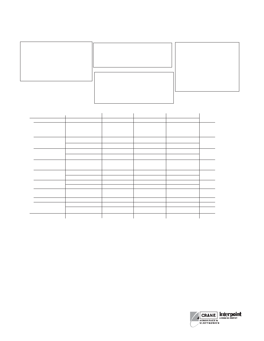
Electrical Characteristics:14 VDC Vin, ±100mA load, unless otherwise specified.
TYPICAL CHARACTERISTICS
Output Voltage Temperature Coefficient
· 100 ppm/°C typical
Isolation
· 100 megohm minimum at 500 V
· Any pin to case except case pin
Audio Rejection 40 dB, typical
Conversion Frequency (kHz)
· 90 min kHz, Vin=6V, ±Iout=60 mA,
Tc=-55 to +125°C
Inhibit Pin Voltage (unit enabled)
· 7 to 8 V
HSH1205D
25°C
+125°C/-55°C
1
+150°C
1
PARAMETER
CONDITIONS
MIN TYP
MAX
MIN
TYP
MAX
MIN
TYP
MAX
UNITS
V
IN
= 6, I
OUT
= ±60mA
±4.75
±5
±5.25
±4.75
±5
±5.25
±4.75
±5
±5.25
OUTPUT VOLTAGE
V
IN
= 16, I
OUT
= ±60mA ±4.75
±5
±5.25
±4.75
±5
±5.25
±4.75
±5
±5.25
VDC
V
IN
= 16, I
OUT
= ±120mA ±4.75
±5
±5.25
±4.75
±5
±5.25
±4.75
±5
±5.25
OUTPUT CURRENT
5
V
IN
= 12 TO 18 VDC
0
±150
240
0
±150
240
0
±100
160
mA
V
IN
= 6 TO 20 VDC
0
±60
96
0
±60
96
0
±60
96
OUTPUT POWER
V
IN
= 12 TO 18 VDC
0
--
1.5
0
--
1.5
0
--
1.0
W
V
IN
= 6 TO 20 VDC
0
--
0.6
0
--
0.6
0
--
0.6
OUTPUT RIPPLE
VOLTAGE
10 kHz - 2 MHz
--
35
180
--
50
250
--
50
250
mV p-p
INPUT VOLTAGE
NO LOAD TO 1.5 W
12
14
18
12
14
18
--
--
--
NO LOAD TO 600 mW
6
14
20
6
14
20
6
14
20
VDC
INPUT CURRENT
NO LOAD
--
5.0
10
--
8
12
--
18
25
mA
INHIBITED
--
2.4
3.2
--
8
12
--
2.4
3.5
INPUT RIPPLE
2
CURRENT
10 kHz - 10 MHz
--
--
50
--
--
100
--
--
100
mA p-p
EFFICIENCY
71
74
--
63
67
--
59
--
--
%
STARTUP
DELAY
--
3
18
--
3
18
--
3
18
ms
OVERSHOOT
1
--
0
100
--
0
150
--
0
150
mV pk
LOAD FAULT
1, 3, 4
POWER DISSIPATION
--
--
2.2
--
--
2.5
--
--
2.5
W
Notes:
1. Guaranteed by design, not tested.
2. Lin = 2 µH.
3. Maximum duration of short circuit: 25°C- 90 seconds, 150°C
5 seconds.
4. Load fault is a short circuit (<50 mohms). Recovery is into
resistive full load.
5. Max. spec indicates 80% of the converter's total power, avail-
able from either output providing the other output carries a
minimum of 20% of the total load.
3
®
HSH 12 05 D / ES
Base Model
Input Voltage
Output Voltage
Screening Level
Number of Outputs
(S = single, D = dual)
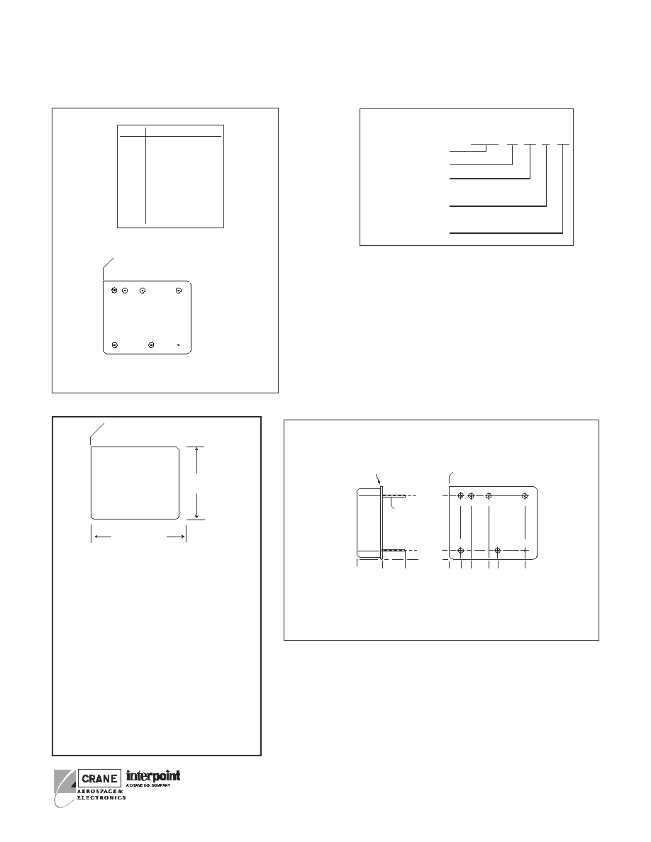
PIN OUT
DC/DC C
ONVERTERS
Pin
Dual Output
1
Positive Input
2
Input Common
3
Positive Output
4
Output Common
5
Case Ground
6
Negative Output
7
Inhibit
MODEL NUMBERING KEY
F
IGURE
1: P
IN
O
UT
Squared corner and dot on
top of cover indicate pin one.
1
4
7
5
2
3
6
CASE A
BOTTOM VIEW
See Figure 3
for pin configurations.
Dot on top of case
indicates pin one.
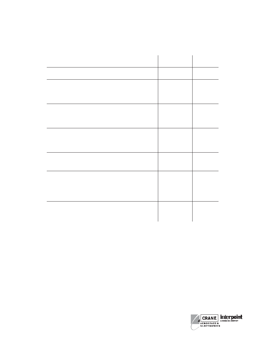
0.980 max
(24.89)
0.805 max
(20.45)
Materials
Header Kovar/Nickel/Gold
(Case A3, Kovar/Nickel)
Cover
Kovar/Nickel
Pins
Kovar/Nickel/Gold,
matched glass seal
Case dimensions in inches (mm)
Tolerance
±0.005 (0.13) for three decimal places
±0.01 (0.3) for two decimal places
unless otherwise specified
CAUTION
Heat from reflow or wave soldering may damage
the device. Solder pins individually with heat
application not exceeding 300
°C for 10 seconds
per pin.
F
IGURE
2: C
ASE
A M
AXIMUM
D
IMENSIONS
0.000
0.097
(2.46)
0.697
(17.70
0.000
0.135 (3.43)
0.835 (21.21)
0.270 max
(6.98)
0.000
1
4
7
5
2
3
6
0.235 (5.97)
0.435 (11.05)
0.535 (13.59)
HSH Series: Screening Standard or ES
BOTTOM VIEW CASE A2
0.27
±
0.02
(6.9
±
0.5)
Projection Weld
Squared corner and dot on
top of case indicate pin one.
0.018
± 0.002 dia.
(0.46
± 0.05)
F
IGURE
3: C
ASE
A2
Note: Although every effort has been made to render the case
drawings at actual size, variations in the printing process may
cause some distortion. Please refer to the numerical dimensions
for accuracy.
HSH SERIES
1.5 WATT
Bottom view
®
4
HSH SERIES
1.5 WATT
TEST HSH
HSH
STANDARD
/ES
PRE-CAP INSPECTION
Method 2017, 2032
yes
yes
TEMPERATURE CYCLE (10 times)
Method 1010, Cond. C, -65°C to 150°C
no
no
Method 1010, Cond. B, -55°C to 125°C
no
yes
CONSTANT ACCELERATION
Method 2001, 3000 g
no
no
Method 2001, 500 g
no
yes
BURN-IN
24 hours at 150°C case (typical)
yes
no
96 hours at 150°C case (typical)
no
yes
FINAL ELECTRICAL TEST MIL-PRF-38534, Group A
Subgroups 1, 2, 4, 5: +25°C, +125°C
yes
yes
HERMETICITY TESTING
Fine Leak, Method 1014, Cond. A
no
yes
Gross Leak, Method 1014, Cond. C
no
yes
Gross Leak, Dip (1 x 10
-3
)
yes
no
FINAL VISUAL INSPECTION
Method 2009
yes
yes
Test methods are referenced to MIL-STD-883 as determined by MIL-PRF-38534.
E
NVIRONMENTAL
S
CREENING
HSH1205D Rev C (25°C eff.). This revision supercedes all previous releases.
All technical information is believed to be accurate, but no responsibility is assumed
for errors or omissions. Interpoint reserves the right to make changes in products
or specifications without notice. HSH Series is a trademark of Interpoint. Copyright
© 2003-2004 Interpoint Corporation. All rights reserved.
Contact Information:
Interpoint USA
Phone:
1-800-822-8782
+425-882-3100
Email:
power@intp.com
www.interpoint.com
Interpoint UK
Phone:
+44-1252-872266
Email:
poweruk@intp.com
Interpoint France
Phone:
+33-134285455
Email:
powerfr@intp.com
DC/DC C
ONVERTERS