 | –≠–ª–µ–∫—Ç—Ä–æ–Ω–Ω—ã–π –∫–æ–º–ø–æ–Ω–µ–Ω—Ç: MK2002812 | –°–∫–∞—á–∞—Ç—å:  PDF PDF  ZIP ZIP |

MODELS
VDC O
UTPUT
B2-3
Size (max.): 2.405 x 2.285 x 0.465 inches (61.09 x 58.04 x 11.81 mm)
See Section B8, case M for dimensions.
Weight:
150 grams typical
Screening: Unscreened or Standard (ST). See Section C2 for
screening options, see Section A5 for ordering information.
SINGLE
5
12
15
DUAL
(+/+, ≠/≠, or ±)
12
15
DESCRIPTION
Interpoint's MK200TM Series DC/DC converters deliver up to 200
watts of output power from an industry standard half-brick package.
The converters operate from -55∞C to +125∞C to satisfy the require-
ments of military, aerospace, and other high-rel applications. As
many as 5 single output converters may be paralleled for up to 900
watts of output power. The wide input voltage range of 19 to 40 VDC
provides full output power, while an extended input range of 16 to 40
VDC is available with derated output power operation from 16 to 19
VDC. Single and dual models deliver outputs of 5, 12, 15, ±12, or
±15 VDC.
C
ONVERTER
D
ESIGN
The MK200 Series of DC/DC converters combines dual-
phase/phase-shifted technology with a single-ended forward
conversion topology. This technology boosts power output without
increases in size and greatly reduces output noise while enhancing
the power density and efficiency of the converter. Packaged in one
module, two converters with parallel power paths operate at the
same frequency but are phase shifted from each other by 180∞. The
result is a conversion frequency twice the switching frequency which
reduces switching noise and allows increased power density. The
dual converter design allows the dual models to be used in any
polarity:
∑ Two positive outputs
∑ Two negative outputs
∑ One negative and one positive output
The MK200 Series converters' planar magnetics use printed
conductors instead of the traditional wire wound magnetics to elim-
inate errors that can occur in winding and provide 100% repro-
ducibility to ensure predictable operation of the converter. Film
capacitors on the input deliver another advantage with their low
ESR (Equivalent Series Resistance) and extremely low ESL
(Equivalent Series Inductance).
N
OISE
M
ANAGEMENT
Reduced switching noise and internal filtering combine to reduce
input ripple to as low as 65 mA peak to peak and output ripple to as
low as 25 mV peak to peak. Audio rejection is typically 35 dB.
R
EMOTE
S
ENSE AND
T
RIM
Remote sense terminals can be connected directly to your load to
compensate for line loss at high power (see Figure 3). All models
also have a trim function to adjust the output voltage. On dual
models, Vout2 is the adjustable output. The output voltage can be
adjusted down to as low as 60% or up to as high as 110%. Refer to
Figures 6 and 7 for connection diagrams and to Table 1 and 2 for
resistor values.
I
NHIBIT AND
S
YNCHRONIZATION
The inhibit and synchronization terminal (pin 4) can be used to
synchronize the MK200 Series converters to a system clock or
another converter. It can also be used to inhibit the converter. Pin 4
is referenced to input common and inhibited through an open
collector interface. When inhibited, the converter's input current is
typically 15 mA while the inhibit terminal draws 1 mA or less. Multiple
units can be synchronized to enhance your system's performance.
Refer to Figure 4 for connection diagram and notes.
P
ROTECTION
F
EATURES
Protection features include soft start, undervoltage lockout and short
circuit protection. By controlling the start-up time, soft start mini-
mizes overshoot and large start-up current draw. Undervoltage
lockout, which typically occurs at 12 VDC, prevents possible
"hiccup" operation at low input voltages. Short circuit protection
limits short circuit current to a maximum of 190% of full load output
current.
P
ACKAGING
Six-sided metal construction provides EMI shielding and heat dissi-
pation in the industry standard half-brick package of 2.405 x 2.285
x 0.465 inches (61.09 x 58.04 x 11.81 mm). Internal silicon compo-
nents are hermetically sealed.
DC/DC C
ONVERTERS
28 V
OLT
I
NPUT
MK200 SERIES
200 WATT
F
EATURES
∑ ≠55∞ to +125∞C operation
∑ 19 to 40 VDC input
∑ Fully Isolated
∑ Optocoupler feedback
∑ Dual converter phase shifted
∑ Fixed frequency, 500 kHz typical
∑ Topology ≠ Single Ended Forward
∑ 50 V for up to 50 ms transient protection
∑ Inhibit and sync functions
∑ Indefinite short circuit protection
∑ Parallel up to 5 single output converters
for up to 900 watts
∑ Remote sense and trim on all models
∑ Up to 86% efficiency
∑ Configurable dual outputs

RECOMMENDED OPERATING CONDITIONS
TYPICAL CHARACTERISTICS
SYNC AND INHIBIT
ABSOLUTE MAXIMUM RATINGS
Input Voltage
∑ 16 to 40 VDC (19 to 40 full power)
Output Power
∑ 150 to 200 watts depending on model
(19 to 40 VDC input)
Lead Soldering Temperature (10 sec per lead)
∑ 300∞C
Storage Temperature Range (Case)
∑ ≠65∞C to +125∞C
B2-4
MK200 SERIES
200 WATT
DC/DC C
ONVERTERS
Undervoltage Lockout
∑ 12 V input typical
Current Limit
∑ 190% of full load maximum
Isolation
∑ 100 megohm minimum at 500 V
Audio Rejection
∑ 35 dB typical
Conversion Frequency
∑ Free run mode 1 MHz equivalent
(interleaved 500 kHz, 2 phase
balanced loads)
∑ External sync range 475 to 525 kHz
Parallel Operation
∑ 90% current sharing accuracy
Electrical Characteristics: 25∞C Tc, 28 VDC Vin, 100% load, free run, unless otherwise specified.
Sync In (450 to 550 kHz)
∑ Logic low 0.8 V max
∑ Logic high 8 VDC ±0.2 V, duty cycle 20%,
AC coupled through 2200 pF
* Referenced to input common
∑ If not used, leave unconnected
Sync Out - Referenced to input common
Inhibit TTL Open Collector
∑ Logic low (output disabled), V =
0.8 V
∑ Referenced to input common
∑ Logic high (output enabled) open collector
MK200-2805
MK200-2812
MK200-2815
MK200-281212
MK200-281515
PARAMETER
CONDITION
1
MIN TYP MAX
MIN
TYP
MAX
MIN TYP MAX
MIN
TYP
MAX
MIN
TYP
MAX UNITS
OUTPUT VOLTAGE
2
4.95 5.00 5.05 11.88 12.00 12.12 14.85 15.00 15.15 ±11.88 ±12.00 ±12.12 ±14.85 ±15.00 ±15.15
VDC
OUTPUT CURRENT
V
IN
= 19 TO 40 VDC
0
--
30
0
--
14.17
0
--
13.3
0
--
±7.08
0
--
±6.67
A
OUTPUT POWER
3
V
IN
= 19 TO 40 VDC
0
--
150
0
--
170
0
--
200
0
--
170
0
--
200
W
V
IN
= 16 TO 19 VDC
0
--
120
0
--
130
0
--
140
0
--
130
0
--
140
OUTPUT RIPPLE
10 kHz - 20 MHz
--
--
300
--
--
300
--
--
400
--
--
300
--
--
400
VOLTAGE
4
10 kHZ- 2 MHz
25∞C
--
25
50
--
30
50
--
35
65
--
40
50
--
60
50
mV p-p
Tc ≠55∞C to +125∞C
--
--
65
--
--
65
--
--
75
--
--
75
--
--
75
LINE REGULATION
4
V
IN
= 19 TO 40 VDC
--
10
25
--
24
40
--
30
50
--
24
60
3
--
30
50
3
mV
LOAD REGULATION
4
10% TO FULL LOAD
--
10
25
--
24
50
--
30
65
--
24
50
3
--
30
65
3
mV
INPUT VOLTAGE
FULL POWER
19
28
40
19
28
40
19
28
40
19
28
40
19
28
40
REDUCED POWER
16
--
19
16
--
19
16
--
19
16
--
19
16
--
19
VDC
TRANSIENT 50 ms
--
--
50
--
--
50
--
--
50
--
--
50
--
--
50
V
INPUT CURRENT
NO LOAD
--
50
100
--
50
60
--
50
60
--
50
60
--
50
60
mA
FULL LOAD
--
6.5
6.7
--
7.14
7.5
--
8.4
8.5
--
7.14
7.5
--
8.4
8.65
A
INHIBITED
--
15
20
--
15
20
--
15
20
--
15
20
--
15
20
mA
INPUT RIPPLE
10 kHz - 20 MHz
--
--
200
--
--
200
--
--
200
--
--
200
--
--
200
CURRENT
5
10 kHz -2 MHz
25∞C
--
65
180
--
75
180
--
75
180
--
75
140
--
75
150
mA p-p
Tc ≠55∞C to +125∞C
--
--
280
--
--
280
--
--
280
--
--
280
--
--
300
EFFICIENCY
81
82
--
84
85
--
84
85
--
84
85
--
84
85
--
%
LOAD FAULT
6
POWER DISS.
OVERLOAD
--
--
45
--
--
45
--
--
45
--
--
32
--
--
32
W
SHORT CIRCUIT
7
--
--
45
--
--
40
--
--
40
--
--
32
--
--
32
RECOVERY
--
--
30
--
--
30
--
--
30
--
--
30
--
--
30
ms
OUTPUT CURRENT
TRIP POINT
--
--
39.0
--
--
18.5
--
--
18.5
--
--
9.5
--
--
9.0
A
SHORT CIRCUIT
7
--
--
46
--
--
27
--
--
24
--
--
±12
--
--
±12
STEP LOAD RESP.
4
50% ≠ 100%
TRANSIENT
--
450
--
750
--
850
--
1200
--
1200
mV pk
RECOVERY
8
--
750
--
750
--
750
--
750
--
750
µs
START-UP
4
DELAY
8
--
35
65
--
40
65
--
40
90
--
5
10
--
5
10
ms
OVERSHOOT
0
0.40 0.60
0
1.00
2.00
--
1.50 2.25
0
0.10
0.50
0
0.10
0.50
V pk
TRIM RANGE
9
3 TO 5.5
7.2 TO 13.2
9 TO 16.5
10 TO 13.2
10
10 TO 16.5
10
VDC
Notes
See "Specification Table Notes," 1 through 10, on the following page.
Input Voltage Range
∑ 16 to 40 VDC (19 to 40 full power) continuous
∑ 50 V for 50 msec transient
Case Operating Temperature (Tc)
∑ ≠55∞C to +125∞C full power
∑ ≠55∞C to +135∞C absolute
Derating: Do not operate above 125∞C case.
PINS NOT IN USE
Share When not used, leave unconnected
Trim
When not used, leave unconnected
Sense When not used, must be connected to
the respective output terminals

B2-5
MK200 SERIES
200 WATT
DC/DC C
ONVERTERS
SPECIFICATION TABLE NOTES
Notes
1. In order to standardize source impedance, the following input filter was used for all tests:
C = 82 µF, L = 0.65 µH, "WIRE" is #18 gauge and 6 inches maximum length.
See Figure 1. Input measurements were taken at "a".
2. On dual output models, outputs can be connected as +/+, ≠/≠, or ±.
3. Tc = ≠55∞C to +125∞C.
4. On dual models the specification applies to each output.
5. On dual models, the specification applies to balanced loads.
6. Load fault conditions are measured with a resistive load.
7 Short circuit is measured with a 50 m
(±10%) load.
8. Time to settle to within 1% of Vout.
9. Refer to trim note 4 under "Notes for Connections" on the following page.
10. Vout2 only.
MK200
L
C
WIRE
a
F
IGURE
1: I
NPUT
F
ILTER
FOR
T
ESTING
PWM
CM
CONTROLLER
PWM
CM
CONTROLLER
Positive
Input
Input
Common
Inh/Sync in
Sync out
Feedback
Feedback
Positive
Output
Negative
Output
Share
100 WATTS
100 WATTS
FB
FB
Positive Sense
Trim
Negative Sense
5
1
4
2
9
3
8
10
6
7
F
IGURE
2: B
LOCK
D
IAGRAM

B2-6
MK200 SERIES
200 WATT
DC/DC C
ONVERTERS
CONNECTIONS
R
T
= trim resistor, V
O
= desired Vout
M
ODEL
% V
OUT
N
OMINAL
+10
+5
≠10
≠20
≠30
≠40
MK200-2805
525
1125
675
225
75
0
MK200-2812
717
2733
7573
2531
851
0
MK200-2815
454
3192
12600
4178
2300
0
MK200-281212
474
3530
5679
N/A
N/A
N/A
MK200-281515 423
3057
9377
2793
598
N/A
TRIM UP
R
T
=
300
≠75
V
O
≠ 5
R
T
= 2420
≠1300
V
O
≠ 12
R
T
=
3920
≠2200
V
O
≠ 15.023
R
T
=
3025
≠2210
V
O
≠ 12.073
R
T
=
3950
≠2210
V
O
≠ 15
TRIM DOWN
R
T
=
150 (V
O
≠2)
≠75
5 ≠ V
O
R
T
=
1210 (V
O
≠2)
≠1300
12 ≠ V
O
R
T
=
1960 (V
O
≠2)
≠2200
15.023 ≠ V
O
R
T
=
1210 (V
O
≠2.5)
≠2210
12.073 ≠ V
O
R
T
= 1580
(V
O
≠2.5)
≠2210
15 ≠ V
O
(
)
(
)
(
)
(
)
(
)
(
)
(
)
(
)
(
)
(
)
MK200≠2805
MK200≠2812
MK200≠2815
MK200≠281212
MK200≠281515
R
load
+Vout 6
+Sense 7
Trim 8
≠Sense 9
≠Vout 10
Trim to Increase Voltage
R
trim
+Vout 6
+Sense 7
Trim 8
≠Sense 9
≠Vout 10
R
load
Trim to Decrease Voltage
R
trim
R
Load
+Vout1 6
≠Vout1 7
Vout2Trim 8
+Vout2 9
≠Vout2 10
Trim to Decrease Voltage
R
trim
R
Load
Trim to Increase Voltage
R
trim
+Vout1 6
≠Vout1 7
Vout2Trim 8
+Vout2 9
≠Vout2 10
F
IGURE
6: S
INGLE
O
UTPUT
T
RIM
C
ONNECTION4
F
IGURE
7: D
UAL
O
UTPUT
T
RIM
C
ONNECTION4
+Vout 6
+Sense 7
Trim 8
≠Sense 9
≠Vout 10
R
load
2,200 pF
Positive
Input
Input
Common
Sync/Inhibit
MK200
Open
Collector
Inhibit
Clock/
Sync Signal
Inhibit Signal
+Vout 6
+Sense 7
Trim 8
≠Sense 9
≠Vout 10
5 +Vin
4 Inh/SyncIn
3 Share
2 SyncOut
1 ≠Vin
R
load
+Vout 6
+Sense 7
Trim 8
≠Sense 9
≠Vout 10
5 +Vin
4 Inh/SyncIn
3 Share
2 SyncOut
1 ≠Vin
+Vout 6
+Sense 7
Trim 8
≠Sense 9
≠Vout 10
5 +Vin
4 Inh/SyncIn
3 Share
2 SyncOut
1 ≠Vin
F
IGURE
5: S
INGLE
O
UTPUT
P
ARALLEL
C
ONNECTION3
F
IGURE
4: I
NHIBIT AND
S
YNC
C
ONNECTION2
F
IGURE
3: S
INGLE
O
UTPUT
S
ENSE
C
ONNECTION1
Notes for Connections
1. Sense: All connections should be made as close to the load as possible
for optimum load regulation. When sense is not used, the sense terminals
must be connected to their respective output terminals (pin 7 to pin 6 and
pin 9 to pin 10).
2. Inhibit and Synchronization: Inhibit/sync in (pin4) and sync out (pin 2) are
referenced to input common (pin 1). Referencing either of these pins to
any other point could result in damage to the converter. To synchronize
the converter, AC couple an 8V peak pulse, 20% duty cycle, sync signal
through a 2200 pF capacitor. The converters sync on the positive edge of
the pulse.
3. Paralleling: Up to five single output converters may be paralleled. Sense
connections should be made as close as possible to the load for optimum
load regulation.
4. Trim: All connections should be made as close to the load as possible for
optimum load regulation. When increasing the output voltage, do not
exceed the maximum output power rating. When decreasing the output
voltage, do not exceed the maximum output current rating. On dual output
models, only Vout2 can be trimmed. Minimum Vout2 is 10 VDC. When
trim pin is not used, leave unconnected.
R
TRIM (
(R
T
) ohms, 1/4 watt
T
ABLE
1: Q
UICK
R
EFERENCE
T
RIM
T
ABLE
2: C
ALCULATED
T
RIM

MODEL NUMBERING KEY
PIN OUT
B2-7
MK200 SERIES
200 WATT
DC/DC C
ONVERTERS
MK200 ≠ 28 12 / ST
Base Model
Input Voltage
Output Voltage
(For dual outputs both outputs are included
≠ MK200-281212 is a 12 volt dual output.)
Screening
(Standard screening has no designator
in this position.)
1
2
3
4
5
6
7
8
9
10
TOP VIEW
(PIN SIDE)
MK200
Pin
Single Output
Dual Output
1
Input Common
Input Common
2
Sync Out
Sync Out
3
Share
No connection
4
Inhibit/Sync In
Inhibit/Sync In
5
Positive Input
Positive Input
6
Positive Output
Positive Vout 1
7
Positive Sense
Negative Vout 1
8
Trim
Vout 2 Trim
9
Sense Return
Positive Vout 2
10
Negative Output
Negative Vout 2
F
IGURE
8: P
IN
O
UT
, P
IN
S
IDE
V
IEW
Typical Performance Curves: 25∞C Tc , 28 VDC Vin, 100% load, free run, unless otherwise specified.
F
IGURE
12
F
IGURE
14
16V
EFFICIENCY vs. LINE & LOAD
0
20
40
60
80
100 120 140 160 180 200
OUTPUT POWER (Watts)
MK200-281212
EFFICIENCY (%)
75
82.5
85
87.5
90
77.5
80
19V
28V
40V
AUDIO REJECTION
ATTENUATION (dB)
≠70
≠60
≠50
≠40
≠20
≠30
FREQUENCY (kHz)
0.1
1
10
100
MK200 SINGLE MODELS
16V
EFFICIENCY vs. LINE & LOAD
0
20
40
60
80 100 120 140 160 180 200
OUTPUT POWER (Watts)
MK200-2805
EFFICIENCY (%)
75
82.5
85
87.5
90
77.5
80
19V
28V
40V
F
IGURE
9
16V
EFFICIENCY vs. LINE & LOAD
0
20
40
60
80
100 120 140 160 180 200
OUTPUT POWER (Watts)
MK200-2812
EFFICIENCY (%)
75
82.5
85
87.5
90
77.5
80
19V
28V
40V
F
IGURE
10
16V
EFFICIENCY vs. LINE & LOAD
0
20
40
60
80
100 120 140 160 180 200
OUTPUT POWER (Watts)
MK200-281515
EFFICIENCY (%)
75
82.5
85
87.5
90
77.5
80
19V
28V
40V
F
IGURE
13
F
IGURE
11
16V
EFFICIENCY vs. LINE & LOAD
0
20
40
60
80
100 120 140 160 180 200
OUTPUT POWER (Watts)
MK200-2815
EFFICIENCY (%)
75
82.5
85
87.5
90
77.5
80
19V
28V
40V
See Section B8, case M for dimensions.

B2-8
MK200 SERIES
200 WATT
DC/DC C
ONVERTERS
Typical Performance Curves: 25∞C Tc , 28 VDC Vin, 100% load, free run, unless otherwise specified.
F
IGURE
18
F
IGURE
20
1V/div.
V
IN
20V/div.
V
OUT
P
OUT
= 150W
TURN-ON INTO FULL LOAD
5
10
15
20
25
30
35
40
45
50
TIME (ms)
MK200-2805
LOAD TRANSIENT RESPONSE
100% TO 10%, 10% TO 100% LOAD
500 mV / div.
1 ms / div.
MK200-2815
100% to 10%
10% to 100%
ATTENUATION (dB)
≠70
≠60
≠50
≠40
≠20
≠30
FREQUENCY (kHz)
0.1
1
10
100
MK200 DUAL MODELS
AUDIO REJECTION
F
IGURE
15
V
IN
LINE TRANSIENT RESPONSE
50 mV / div.
50
µ
s / div.
10 V / div.
V
out
MK200-2805
F
IGURE
16
V
IN
LINE TRANSIENT RESPONSE
100 mV / div.
50
µ
s / div.
10 V / div.
V
out
MK200-2815
F
IGURE
19
F
IGURE
17
1V/div.
V
IN
20V/div.
V
OUT
P
OUT
= 150W
TURN-ON INTO FULL LOAD
5
10
15
20
25
30
35
40
45
50
TIME (ms)
MK200-2805
F
IGURE
24
F
IGURE
26
V
IN
LINE TRANSIENT RESPONSE
100 mV / div.
100
µ
s / div.
10 V / div.
V
OUT
2
MK200-281515
V
OUT
1
15.5
15
14.5
14
13.5
13
80
100
120
90
110
130
140
MK200-281212
MK200-281515
INPUT VOLTAGE
OUTPUT POWER
MK200 DUAL MODELS
LOW LINE DROPOUT vs. LOAD
2V/div.
V
IN
20V/div.
V
OUT
P
OUT
= 200W
TURN-ON INTO FULL LOAD
5
10
15
20
25
30
35
40
45
50
TIME (ms)
MK200-2815
F
IGURE
21
LOAD TRANSIENT RESPONSE
100% TO 10%, 10% TO 100% LOAD
500 mV / div.
1 ms / div.
MK200-281212
100% to 10%
10% to 100%
V
OUT
1 / V
OUT
2
V
OUT
1 / V
OUT
2
F
IGURE
22
INPUT VOLTAGE
OUTPUT POWER
MK200 SINGLE MODELS
LOW LINE DROPOUT vs. LOAD
15.5
15
14.5
14
13.5
13
80
100
120
90
110
130
140
MK200-2805
MK200-2812
MK200-2815
F
IGURE
25
F
IGURE
23
2V/div.
V
IN
20V/div.
V
OUT
1
P
OUT
= 170W
TURN-ON INTO FULL LOAD
2
4
6
8
10
12
14
16
18
20
TIME (ms)
MK200-281212
V
OUT
2
12001-001-DTS Rev A
DQ# 1001
All technical information is believed to be accurate, but no responsibility is
assumed for errors or omissions. Interpoint reserves the right to make changes in
products or specifications without notice. MK200 is a trademark of Interpoint.
Copyright © 1995-1999 Interpoint. All rights reserved.
B8-33
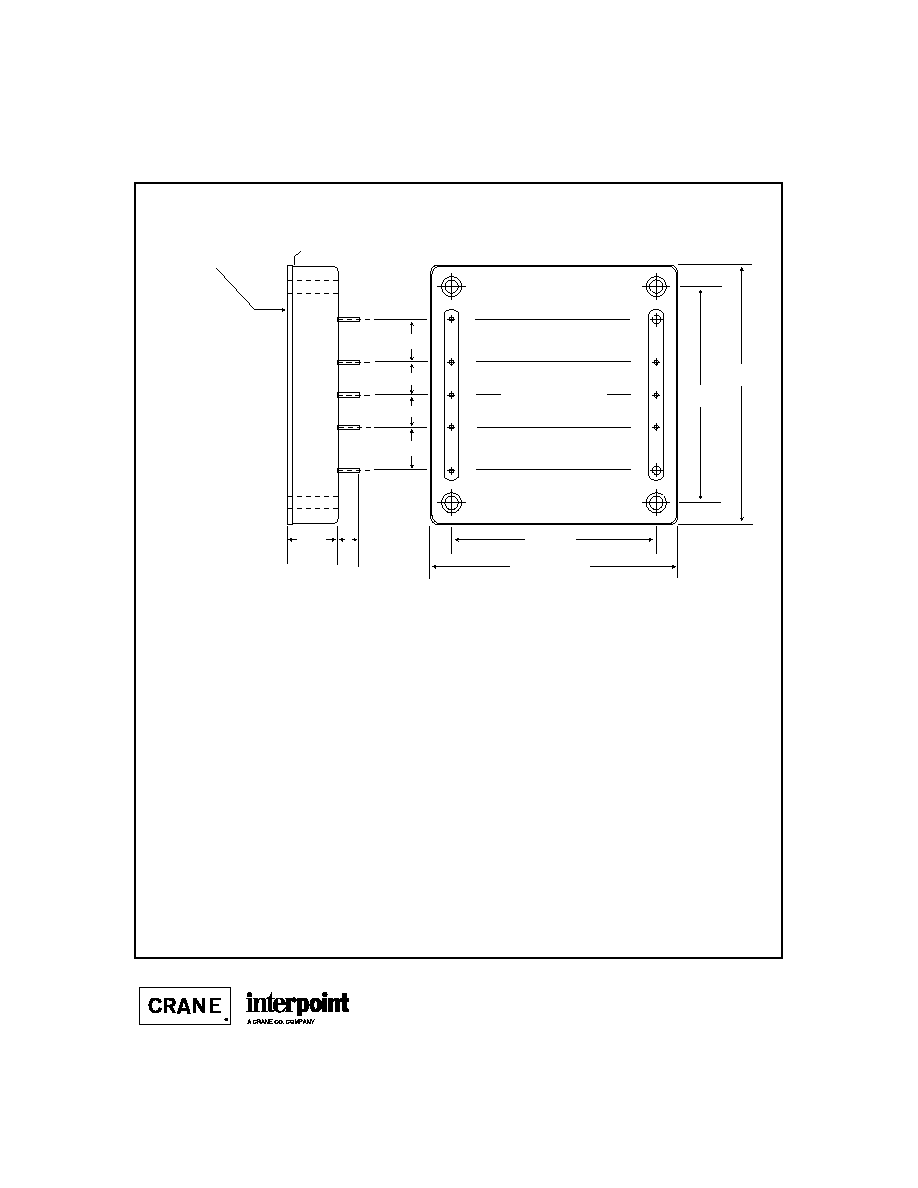
CASE M
C
ASES
Materials
Header Cold Rolled Steel/Polymide Insulator/
Copper/Nickel/Gold
Cover
Cold Rolled Steel/Nickel/Black Epoxy Powder
Pins Copper/Nickel/Gold
Solder attached
Cover is epoxy attached and filled.
Case dimensions in inches (mm)
Tolerance
±
0.005 (0.13) for three decimal places
±
0.01 (0.2) for two decimal places
unless otherwise specified
CAUTION
Heat from reflow or wave soldering may damage
the device. Solder pins individually with heat
application not exceeding 300
∞
C for 10 seconds
per pin. Due to the high conductivity of the pins,
a high power soldering iron is recommended to
meet time and temperature requirements.
Overheating may cause the solder attach to
reflow and loosen the pins.
Epoxy Attach
Uncoated metal header.
Use this side for heat sinking.
1
2
3
4
5
6
7
8
9
10
0.40 (10.2)
0.40 (10.2)
0.30 (7.6)
0.30 (7.6)
2.285 max (58.04)
2.405 max
(61.09)
1.90 (48.3)
2.00
(50.8)
0.20 min (5.1)
0.465 max
1
1.81)
Pin diameter: 0.04 (1.0) pins 1- 5 and 7 - 9
0.08 (2.0) pins 6 and 10
CASE M
TOP VIEW
(PIN SIDE)
Mounting Hole
Mounting Hole
MK200 Series: Screening ≠ Standard or ST
PIN-SIDE VIEW CASE M
F
IGURE
51: C
ASE
M

C2-11
QA SCREENING
MK200 SERIES
TEST (MK200 only)
Standard
ST
PRE-COVER VISUAL
Per IPC-610A, Class III
yes
yes
TEMPERATURE CYCLE (10 times)
Per MIL-STD-883 as determined by MIL-PRF-38534
Method 1010, Cond. B, ≠-55∞C to 125∞C
no
yes
BURN-IN
Per MIL-STD-202, Method 108, Cond. A
no
yes
FINAL ELECTRICAL TEST
Per Interpoint's Acceptance Test Procedure
+25∞C
yes
yes
≠55∞C and +125∞C
no
yes
HERMETICITY TESTING
Gross Leak, Dip
no
yes
FINAL VISUAL INSPECTION
Per MIL-STD-883 as determined by MIL-PRF-38534
Method 2009
yes
yes
MK 200 S
ERIES
Applies only to the MK200 Series.