 | –≠–ª–µ–∫—Ç—Ä–æ–Ω–Ω—ã–π –∫–æ–º–ø–æ–Ω–µ–Ω—Ç: SLIM5050 | –°–∫–∞—á–∞—Ç—å:  PDF PDF  ZIP ZIP |
B1-11
SLIM SERIES
50 - 250 WATT
L
INE
I
NTERFACE
M
ODULE
40
TO
80 VDC I
NPUT
50
OR
250 W
ATT
O
UTPUT
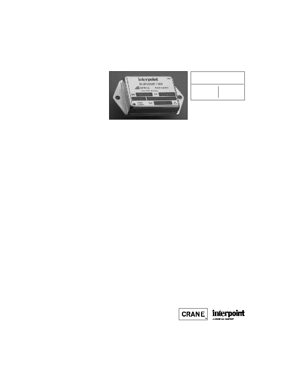
SLIM5050
Size (max.): Non flanged
1.460 x 1.130 x 0.330 (37.08 x 28.70 x 8.38 mm)
Flanged
2.005 x 1.130 x 0.330 (50.93 x 28.70 x 8.38 mm)
See Section B8, cases E1 and G1, for dimensions.
Weight:
30 grams typical
Screening:
Standard, Class H, or Class K (MIL-PRF-38534)
Radiation hardness levels O, L, and R
Section C2 for screening and radiation hardness
options, see Section A5 for ordering information.
F
EATURES
∑ Fully qualified to Class H or K
∑ Radiation hardened
∑ -55∞C to +125∞C operating temp
∑ 40 to 80 VDC input
∑ Fixed frequency, 550 kHz typical
∑ Topology ≠ Non-isolated buck
∑ 35 VDC input with lowered efficiency
∑ Up to 90 V for up to 120 ms
transient protection
∑ 35 VDC output
∑ Inhibit function
∑ Power readiness function
∑ Load fault/short circuit protection
∑ Up to 94% efficiency, 90 W/in
3
MODEL
THROUGHPUT POWER
MODEL
SLIM5050TM
SLIM50250TM
WATTS
50
250
DESCRIPTION
The SLIM50TM Series of line interface modules for space provide a
nominal output voltage of 35 VDC from input voltages of 45 to 75
VDC with efficiencies of 94% or higher. Sustained operation at volt-
ages as high at 80 or as low as 35 are possible with reduced effi-
ciency. The SLIM5050 module delivers 50 watts of output power
over the full military temperature range of ≠55∞C to +125∞C and fits
in a package of 1.460 x 1.130 x 0.330 inches (37.08 x 28.70 x 8.38
mm) maximum, resulting in a power density of over 91 watts/in
3
.
S
CREENING AND
R
EPORTS
The SLIM5050 module offers three screening options ≠ Standard,
Class H, or Class K ≠ and three levels of radiation hardness. See
Section C2, Quality Assurance, pages C2-7 through C2-9, for
descriptions. Detailed reports on product performance are also
available and are listed on page C2-9.
C
ONVERTER
D
ESIGN
The SLIM5050 modules are non-isolated converters operating at a
frequency between 500 kHz and 600 kHz. The control circuitry uses
average current mode control to achieve a wide bandwidth with little
or no overshoot over a wide range of loads. These converters are
specifically designed to accommodate loads with a negative imped-
ance such as those presented by Interpoint DC/DC converters with
a constant power consumption.
P
ARALLEL
O
PERATION
: U
P TO
10 M
ODULES
Up to 10 SLIM SeriesTM modules can be paralleled for increased
power. Current sharing is typically within 2%.
O
VERLOAD AND
C
URRENT
L
IMIT
Current overload protection is accomplished by monitoring the
output current resulting in a constant current mode when the load
exceeds approximately 125% of rated load at full output voltage.
When the overload condition forces the output voltage to drop the
maximum current delivered falls from approximately 1.9 amps to
less than 1.5 amps. This feature keeps the short circuit dissipation
low and forces the output voltage to collapse rapidly thereby
preventing operation in an abnormal condition. Combined with the
"Power Ready" signal (see below), this foldback of the output
current prevents power cycling of the downstream converters.
P
OWER
R
EADY
S
IGNAL
To avoid high current surges during power up, the interface module
has a signal intended to connect to the inhibit lines of Interpoint
converters to keep these converters turned off until the interface
module's output exceeds approximately 13 volts thereby assuring
that, in an overload condition, the converters powered by the inter-
face module will shut off before the power ready signal turns them
off. This feature prevents repeated limit cycling in an overload condi-
tion.
I
NHIBIT
The SLIM Series modules have an open collector TTL compatible
inhibit terminal that can be used to disable power conversion,
resulting in a very low quiescent input current and no generation of
switching noise.
Future offerings are planned for the SLIM Series of modules.
Please contact your Interpoint representative listed in Section
A5, for more details.
All technical information is believed to be accurate, but no responsibility is assumed for errors
or omissions. Interpoint reserves the right to make changes in products or specifications
without notice. SLIM Series, SLIM50, SLIM5050, and SLIM50250 are trademarks of Interpoint.
Copyright © 1999 Interpoint. All rights reserved.

B8-10
CASE E
C
ASES
CASE E
BOTTOM VIEW
See Figures 16 ≠ 18
for pin configurations.
Squared corner and dot on top
of case indicate pin one.
1.460 max
(37.08)
1.130 max
(28.70)
Materials
Header Cold Rolled Steel/Nickel/Gold
Cover Kovar/Nickel
(SMHF Series
Cold Rolled Steel/Nickel/Gold)
Pins #52
alloy/Gold
compression glass seal
Case dimensions in inches (mm)
Tolerance
±
0.005 (0.13) for three decimal places
±
0.01 (0.3) for two decimal places
unless otherwise specified
CAUTION
Heat from reflow or wave soldering may damage
the device. Solder pins individually with heat
application not exceeding 300
∞
C for 10 seconds
per pin.
0.000
0.205
(5.21)
0.505
(12.83)
0.705
(17.91)
0.905
(22.99)
1.105
(28.07)
0.330 max
(8.38)
0.000
0.25 (6.35)
0.000
0.160
(4.06)
0.960
(24.38)
1
2
3
4
5
0.030 dia.
(0.76)
8
7
6
MHF+ Series Single and Dual: Screening ≠ Standard, ES, or 883
MHF Series and LIM5050 Module: Screening ≠ Standard or ES
SMHF Series Single and Dual and SLIM5050 Module:
Screening ≠ Space Standard, H, or K
HR120 Series: No screening options
BOTTOM VIEW CASE E1
0.330 max
(8.38)
0.000
0.25 (6.35)
Projection Weld
Seam Seal
Squared corner and dot on top
of case indicate pin one.
F
IGURE
16: C
ASE
E1
F
IGURE
15: C
ASE
E M
AXIMUM
D
IMENSIONS
Note: Although every effort has been made to render the case drawings at actual size, variations in the printing process may cause some distortion. Please refer
to the numerical dimensions for accuracy.

B8-15
CASE G
C
ASES
Materials
Header Cold Rolled Steel/Nickel/Gold
Cover
MHF+ Series and FMH Filter
Kovar/Nickel
SMHF
Cold Rolled Steel/Nickel
Pins
#52 alloy (all cases)
compression glass seal
Case dimensions in inches (mm)
Tolerance
±
0.005 (0.13) for three decimal places
±
0.01 (0.2) for two decimal places
unless otherwise specified
CASE G
BOTTOM VIEW
Flanged package
See Figures 25 - 27
for pin configuration
2.005 max
(50.93)
1.130 max
(28.70)
Squared corner and dot on top
of case indicate pin one.
CAUTION
Heat from reflow or wave soldering may damage
the device. Solder pins individually with heat
application not exceeding 300
∞
C for 10 seconds
per pin.
Flange Thickness: 0.047 (1.19)
1.590 (40.39)
0.128 dia
(3.25)
0.030 dia.
(0.76)
Flanged cases: Designator required in Case Option position of model number
MHF+ Series Single and Dual, LIM5050 Module: Screening ≠ Standard, ES, or 883
SMHF Series, SLIM5050 Module: Screening ≠ Space Standard, H, or K
BOTTOM VIEW CASE G1
0.000
0.205 (5.21)
0.505 (12.83)
0.705 (17.91)
0.905 (22.99)
1.105 (28.07)
0.000
0.160
(4.06)
0.960
(24.38)
1
2
3
4
5
8
7
6
0.140 (3.56)
0.560
(14.22)
0.330 max.
(8.38)
0.000
0.25 (6.35)
0.330 max.
(8.38)
0.000
0.25 (6.35)
Squared corner and dot on top
of case indicate pin one.
Projection Weld
Seam Seal
F
IGURE
25: C
ASE
G1
F
IGURE
24: C
ASE
G M
AXIMUM
D
IMENSIONS
Note: Although every effort has been made to render the case drawings at actual size, variations in the printing process may cause some distortion. Please refer
to the numerical dimensions for accuracy.
C2-7
QA SCREENING
SPACE PRODUCTS
S
PACE
P
RODUCTS
E
LEMENT
E
VALUATION
S
TANDARD
C
LASS
C
LASS
T
EST
P
ERFORMED
(O)
H
K
(
COMPONENT LEVEL
)
M/S
P
M/S
P
M/S
P
Element Electrical
yes
no
yes
yes
yes
yes
Element Visual
no
no
yes
yes
yes
yes
Internal Visual
no
no
yes
no
yes
no
Temperature Cycling
no
no
no
no
yes
yes
Constant Acceleration
no
no
no
no
yes
yes
Interim Electrical
no
no
no
no
yes
no
Burn-in
no
no
no
no
yes
no
Post Burn-in Electrical
no
no
no
no
yes
no
Steady State Life
no
no
no
no
yes
no
Voltage Conditioning /Aging
no
no
no
no
no
yes
Visual Inspection
no
no
no
no
no
yes
Final Electrical
no
no
yes
yes
yes
yes
Wire Bond Evaluation
*
no
no
yes
yes
yes
yes
SEM
no
no
no
no
yes
no
SLAMTM/C-SAM:
Input capacitors only
no
no
no
yes
no
yes
(Add'l test, not req. by H or K)
Definitions
Element Evaluation: Component testing/screening per MIL-STD-883 as determined by MIL-PRF-38534
SEM: Scanning Electron Microscopy
SLAMTM: Scanning Laser Acoustic Microscopy
C-SAM: C - Mode Scanning Acoustic Microscopy
Notes
M/S
Active components (Microcircuit and Semiconductor Die)
P
Passive components
*
Not applicable to EMI filters that have no wirebonds
SMFLHP Series
SMFL Series
SMHP Series (O&H only)
SMTR Series
SSP Series
SMHF Series
SMSA Series
SLH Series
SLIM Module
SFME120 EMI Filter
SFME28 EMI Filter
SFCS EMI Filter
SFMC EMI Filter
STF EMI Filter
Applies to the following products:
C2-8
QA SCREENING
SPACE PRODUCTS
E
NVIRONMENTAL
S
CREENING
T
EST
P
ERFORMED
S
TANDARD
C
LASS
C
LASS
(
END ITEM LEVEL
)
(O)
H
K
Non-destruct bond pull*
Method 2023
no
no
yes
Pre-cap inspection
Method 2017, 2032
yes
yes
yes
Temperature cycle
Method 1010, Cond. C
yes
yes
yes
Constant acceleration
Method 2001, 3000 g
yes
yes
yes
PIND Test
Method 2020, Cond. B
no
no
yes
Radiography
Method 2012
no
no
yes
Pre burn-in test
yes
yes
yes
Burn-in, Method 1015, 125∞C
96 hours
yes
no
no
160 hours
no
yes
no
2 x 160 hour (includes mid BI test)
no
no
yes
Final electrical test
MIL-PRF-38534, Group A
yes
yes
yes
Hermeticity test
Fine Leak,
Method 1014, Cond. A
yes
yes
yes
Gross Leak,
Method 1014, Cond. C
yes
yes
yes
Final visual inspection
Method 2009
yes
yes
yes
Test methods are referenced to MIL-STD-883 as determined by MIL-PRF-38534.
Note
* Not applicable to EMI filters that have no wirebonds.
SMFLHP Series
SMFL Series
SMHP Series (O&H only)
SMTR Series
SSP Series
SMHF Series
SMSA Series
SLH Series
SLIM Module
SFME120 EMI Filter
SFME28 EMI Filter
SFCS EMI Filter
SFMC EMI Filter
STF EMI Filter
Applies to the following products:

C2-9
QA SCREENING
SPACE PRODUCTS
PRODUCT LEVEL AVAILABILITY
ENVIRONMENTAL SCREENING LEVELS
STANDARD CLASS
CLASS
RADIATION HARDNESS LEVELS
(O)
H
K
O: Standard, no radiation guarantee
For system evaluation, electrically
OO
HO
Not
and mechanically comparable to
available
H and K level.
L: Radiation hardened ≠ Tested lots
Not
Up to 50 k Rads (Si) total dose
available
HL
KL
No SEU guarantee
R: Radiation hardened ≠ Tested lots
Not
Up to 100 k Rads (Si) total dose
available
HR
KR
SEU guarantee up to 40 MeV
R
EPORTS
: I
NCLUDED WITH PURCHASE OF PRODUCT
HL, KL, HR, or KR
1.Radiation Susceptibility Analysis
2.Electrical/Thermal Stress Analysis and Derating Report
3.MTBF Report
4.FMEA Report
OO option: Select reports available as separate purchases.
R
ADIATION
H
ARDNESS
L
EVELS
FOR
DC/DC C
ONVERTERS AND
L
INE
I
NPUT
M
ODULES1
Note
1. Interpoint's EMI filters are designed exclusively with passive components providing
maximum tolerance for space environment requirements.
SMFLHP Series (levels O and L only)
SMFL Series (levels O and L only)
SMTR Series
SSP Series
SMHF Series
SMSA Series
SLH Series
SLIM Series Modules
Applies to the following products:
L and R are referenced to MIL-PRF-38534, appendix G, Radiation Hardness
Assurance (RHA) levels.