1
CD4017BMS, CD4022BMS
CMOS Counter/Dividers
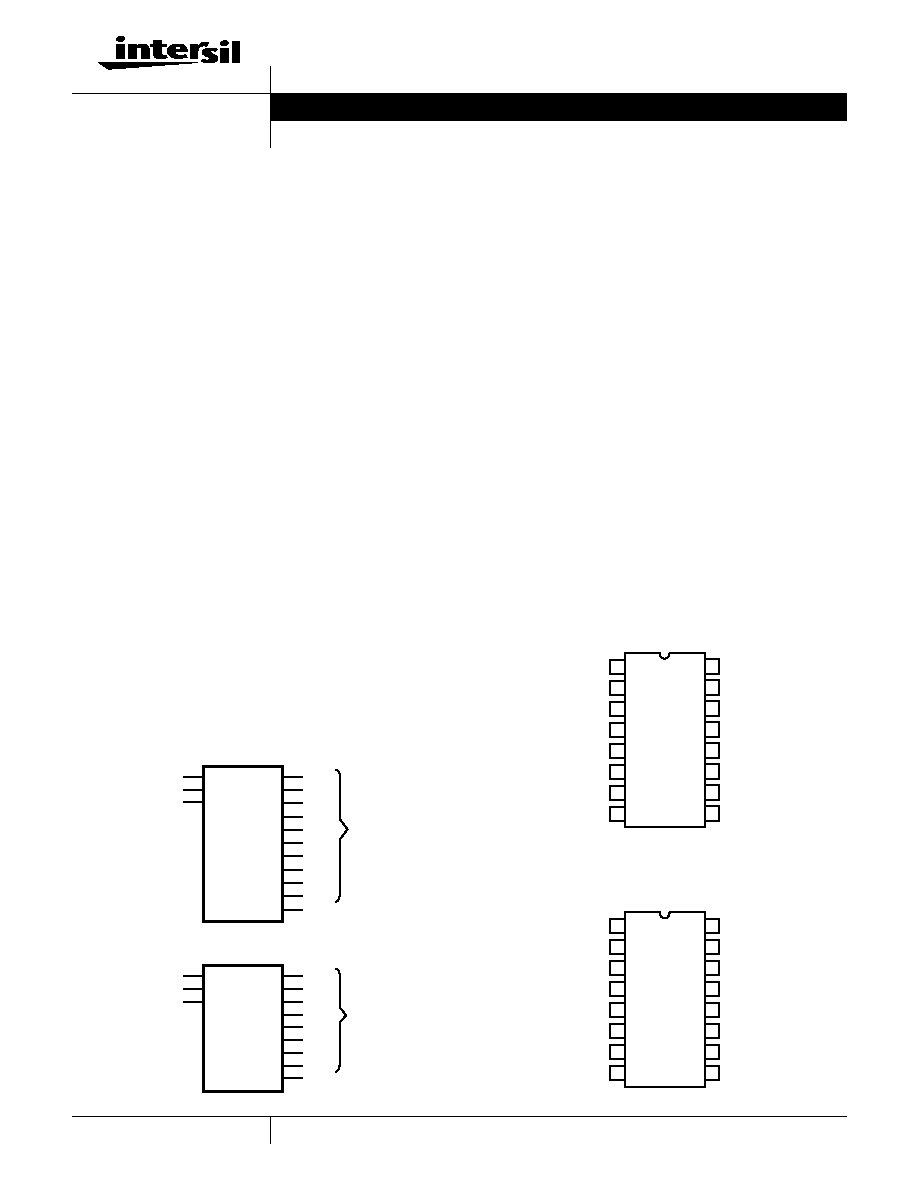
CD4017BMS and CD4022BMS are 5-stage and 4-stage
Johnson counters having 10 and 8 decoded outputs, respec-
tively. Inputs include a CLOCK, a RESET, and a CLOCK INHIBIT
signal. Schmitt trigger action in the CLOCK input circuit provides
pulse shaping that allows unlimited clock input pulse rise and fall
times.
These counters are advanced one count at the positive clock sig-
nal transition if the CLOCK INHIBIT signal is low. Counter
advancement via the clock line is inhibited when the CLOCK
INHIBIT signal is high. A high RESET signal clears the counter to
its zero count. Use of the Johnson counter configuration permits
high speed operation, 2-input decode gating and spike-free
decoded outputs. Anti-lock gating is provided, thus assuring
proper counter sequence. The decoded output are normally low
and go high only at their respective decoded time slot. Each
decoded output remains high for one full clock cycle. A CARRY-
OUT signal completes one cycle every 10 clock input cycles in
the CD4017BMS or every 8 clock input cycles in the
CD4022BMS and is used to ripple-clock the succeeding device
in a multi-device counting chain.
The CD4017BMS and CD4022BMS series types are supplied in
these 16 lead outline packages
Features
∑ High Voltage Types (20V Rating)
∑ Fully Static Operation
∑ Medium-Speed Operation 10MHz (Typ) at VDD = 10V
∑ Standardized Symmetrical Output Characteristics
∑ 100% Tested for Quiescent Current at 20V
∑ 5V, 10V and 15V Parametric Ratings
∑ Meets All Requirements of JEDEC Tentative Standard
Number 13A, "Standard Specifications for Description
of `B' Series CMOS Devices"
Applications
∑ Decade Counter/Decimal Decode Display (CD4017BMS)
∑ Binary Counter/Decoder
∑ Frequency Division
∑ Counter Control/Timers
∑ Divide-by-N Counting
∑ For Further Application Information, See ICAN-6166
"COS/MOS MSI Counter and Register Design and
Applications"
CD4017BMS - Decade Counter with 10 Decoded Outputs
CD4022BMS - Octal Counter with 8 Decoded Outputs
Braze Seal DIP
*H4W
H4X
Frit Seal DIP
*H1F
H1E
Ceramic Flatpack
H6W
*CD4017B Only
CD4022B Only
Functional Diagrams
CD4017BMS
CD4022BMS
3
2
4
7
10
1
5
6
9
"0"
"1"
"2"
"3"
"4"
"5"
"6"
"7"
CARRY OUT
DECODED
DECIMAL
14
13
15
CLOCK
CLOCK INHIBIT
RESET
VCC = 16
VSS = 8
11
12
"8"
"9"
OUT
2
1
3
7
11
4
5
10
12
"0"
"1"
"2"
"3"
"4"
"5"
"6"
"7"
CARRY OUT
DECODED
OUT
14
13
15
CLOCK
CLOCK INHIBIT
RESET
VCC = 16
VSS = 8
Pinouts
CD4017BMS
TOP VIEW
CD4022BMS
TOP VIEW
14
15
16
9
13
12
11
10
1
2
3
4
5
7
6
8
5
1
0
2
6
7
VSS
3
VDD
CLOCK
CLOCK INHIBIT
CARRY OUT
9
4
8
RESET
NC = NO
CONNECTION
14
15
16
9
13
12
11
10
1
2
3
4
5
7
6
8
1
0
2
5
6
NC
VSS
3
VDD
CLOCK
CLOCK INHIBIT
CARRY OUT
4
7
NC
RESET
NC = NO
CONNECTION
Data Sheet
August 1998
File Number
3297
CAUTION: These devices are sensitive to electrostatic discharge; follow proper IC Handling Procedures.
1-888-INTERSIL or 321-724-7143 | Copyright © Intersil Corporation 1999

2
Absolute Maximum Ratings
Reliability Information
DC Supply Voltage Range, (VDD) . . . . . . . . . . . . . . . . -0.5V to +20V
(Voltage Referenced to VSS Terminals)
Input Voltage Range, All Inputs . . . . . . . . . . . . . -0.5V to VDD +0.5V
DC Input Current, Any One Input
. . . . . . . . . . . . . . . . . . . . . . . . .±
10mA
Operating Temperature Range . . . . . . . . . . . . . . . -55
o
C to +125
o
C
Package Types D, F, K, H
Storage Temperature Range (TSTG). . . . . . . . . . . -65
o
C to +150
o
C
Lead Temperature (During Soldering) . . . . . . . . . . . . . . . . . +265
o
C
At Distance 1/16
±
1/32 Inch (1.59mm
±
0.79mm) from case for
10s Maximum
Thermal Resistance. . . . . . . . . . . . . . . .
ja
jc
Ceramic DIP and FRIT Package . . . .
80
o
C/W
20
o
C/W
Flatpack Package . . . . . . . . . . . . . . . .
70
o
C/W
20
o
C/W
Maximum Package Power Dissipation (PD) at +125
o
C
For TA = -55
o
C to +100
o
C (Package Type D, F, K) . . . . . .500mW
For TA = +100
o
C to +125
o
C (Package Type D, F, K) . . . . . Derate
Linearity at 12mW/
o
C to 200mW
Device Dissipation per Output Transistor. . . . . . . . . . . . . . . .100mW
For TA = Full Package Temperature Range (All Package Types)
Junction Temperature . . . . . . . . . . . . . . . . . . . . . . . . . . . . . .+175
o
C
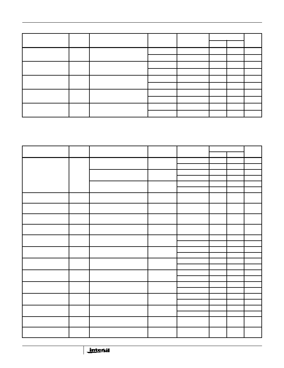
TABLE 1. DC ELECTRICAL PERFORMANCE CHARACTERISTICS
PARAMETER
SYMBOL
CONDITIONS (NOTE 1)
GROUP A
SUBGROUPS
TEMPERATURE
LIMITS
UNITS
MIN
MAX
Supply Current
IDD
VDD = 20V, VIN = VDD or GND
1
+25
o
C
-
10
µ
A
2
+125
o
C
-
1000
µ
A
VDD = 18V, VIN = VDD or GND
3
-55
o
C
-
10
µ
A
Input Leakage Current
IIL
VIN = VDD or GND
VDD = 20
1
+25
o
C
-100
-
nA
2
+125
o
C
-1000
-
nA
VDD = 18V
3
-55
o
C
-100
-
nA
Input Leakage Current
IIH
VIN = VDD or GND
VDD = 20
1
+25
o
C
-
100
nA
2
+125
o
C
-
1000
nA
VDD = 18V
3
-55
o
C
-
100
nA
Output Voltage
VOL15
VDD = 15V, No Load
1, 2, 3
+25
o
C, +125
o
C, -55
o
C
-
50
mV
Output Voltage
VOH15
VDD = 15V, No Load (Note 3)
1, 2, 3
+25
o
C, +125
o
C, -55
o
C
14.95
-
V
Output Current (Sink)
IOL5
VDD = 5V, VOUT = 0.4V
1
+25
o
C
0.53
-
mA
Output Current (Sink)
IOL10
VDD = 10V, VOUT = 0.5V
1
+25
o
C
1.4
-
mA
Output Current (Sink)
IOL15
VDD = 15V, VOUT = 1.5V
1
+25
o
C
3.5
-
mA
Output Current (Source)
IOH5A
VDD = 5V, VOUT = 4.6V
1
+25
o
C
-
-0.53
mA
Output Current (Source)
IOH5B
VDD = 5V, VOUT = 2.5V
1
+25
o
C
-
-1.8
mA
Output Current (Source)
IOH10
VDD = 10V, VOUT = 9.5V
1
+25
o
C
-
-1.4
mA
Output Current (Source)
IOH15
VDD = 15V, VOUT = 13.5V
1
+25
o
C
-
-3.5
mA
N Threshold Voltage
VNTH
VDD = 10V, ISS = -10
µ
A
1
+25
o
C
-2.8
-0.7
V
P Threshold Voltage
VPTH
VSS = 0V, IDD = 10
µ
A
1
+25
o
C
0.7
2.8
V
Functional
F
VDD = 2.8V, VIN = VDD or GND
7
+25
o
C
VOH >
VDD/2
VOL <
VDD/2
V
VDD = 20V, VIN = VDD or GND
7
+25
o
C
VDD = 18V, VIN = VDD or GND
8A
+125
o
C
VDD = 3V, VIN = VDD or GND
8B
-55
o
C
Input Voltage Low
(Note 2)
VIL
VDD = 5V, VOH > 4.5V, VOL < 0.5V
1, 2, 3
+25
o
C, +125
o
C, -55
o
C
-
1.5
V
Input Voltage High
(Note 2)
VIH
VDD = 5V, VOH > 4.5V, VOL < 0.5V
1, 2, 3
+25
o
C, +125
o
C, -55
o
C
3.5
-
V
Input Voltage Low
(Note 2)
VIL
VDD = 15V, VOH > 13.5V,
VOL < 1.5V
1, 2, 3
+25
o
C, +125
o
C, -55
o
C
-
4
V
Input Voltage High
(Note 2)
VIH
VDD = 15V, VOH > 13.5V,
VOL < 1.5V
1, 2, 3
+25
o
C, +125
o
C, -55
o
C
11
-
V
NOTES: 1. All voltages referenced to device GND, 100% testing being im-
plemented.
2. Go/No Go test with limits applied to inputs
3. For accuracy, voltage is measured differentially to VDD. Limit is
0.050V max.
CD4017BMS, CD4022BMS
3
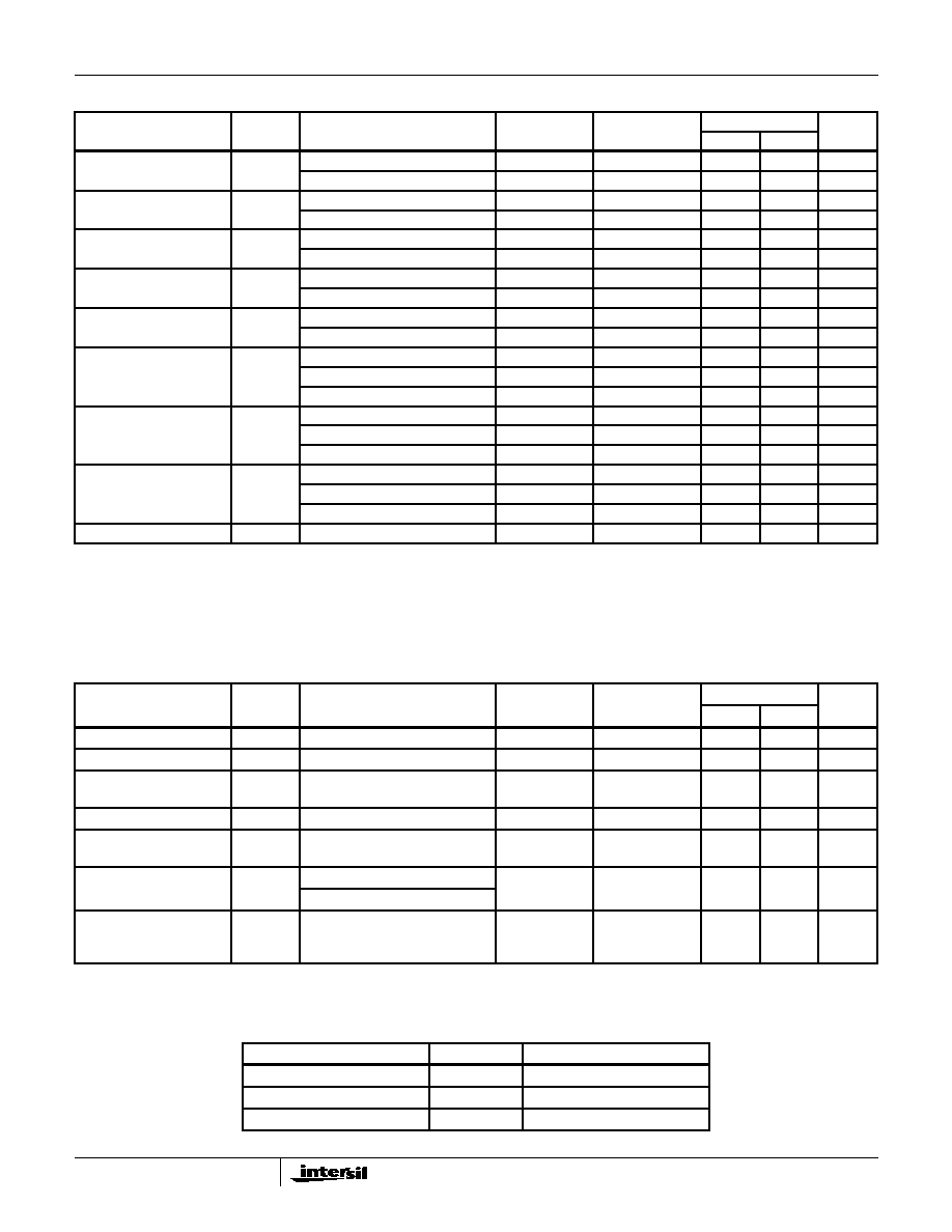
TABLE 2. AC ELECTRICAL PERFORMANCE CHARACTERISTICS
PARAMETER
SYMBOL
CONDITIONS (Note 1, 2)
GROUP A
SUBGROUPS
TEMPERATURE
LIMITS
UNITS
MIN
MAX
Propagation Delay
Clock to Decode Out
TPHL1
TPLH1
VDD = 5V, VIN = VDD or GND
9
+25
o
C
-
650
ns
10, 11
+125
o
C, -55
o
C
-
878
ns
Propagation Delay
Clock to Carry Out
TPHL2
TPLH2
VDD = 5V, VIN = VDD or GND
9
+25
o
C
-
600
ns
10, 11
+125
o
C, -55
o
C
-
810
ns
Propagation Delay
Reset to Out
TPHL3
TPLH3
VDD = 5V, VIN = VDD or GND
9
+25
o
C
-
530
ns
10, 11
+125
o
C, -55
o
C
-
716
ns
Transition Time
TTHL
TTLH
VDD = 5V, VIN = VDD or GND
9
+25
o
C
-
200
ns
10, 11
+125
o
C, -55
o
C
-
270
ns
Maximum Clock Input Fre-
quency
FCL
VDD = 5V, VIN = VDD or GND
9
+25
o
C
2.5
-
MHz
10, 11
+125
o
C, -55
o
C
1.85
-
MHz
NOTES:
1. CL = 50pF, RL = 200K, Input TR, TF < 20ns.
2. -55
o
C and +125
o
C limits guaranteed, 100% testing being implemented.
TABLE 3. ELECTRICAL PERFORMANCE CHARACTERISTICS
PARAMETER
SYMBOL
CONDITIONS
NOTES
TEMPERATURE
LIMITS
UNITS
MIN
MAX
Supply Current
IDD
VDD = 5V, VIN = VDD or GND
1, 2
-55
o
C, +25
o
C
-
5
µ
A
+125
o
C
-
150
µ
A
VDD = 10V, VIN = VDD or GND
1, 2
-55
o
C, +25
o
C
-
10
µ
A
+125
o
C
-
300
µ
A
VDD = 15V, VIN = VDD or GND
1, 2
-55
o
C, +25
o
C
-
10
µ
A
+125
o
C
-
600
µ
A
Output Voltage
VOL
VDD = 5V, No Load
1, 2
+25
o
C, +125
o
C, -
55
o
C
-
50
mV
Output Voltage
VOL
VDD = 10V, No Load
1, 2
+25
o
C, +125
o
C, -
55
o
C
-
50
mV
Output Voltage
VOH
VDD = 5V, No Load
1, 2
+25
o
C, +125
o
C, -
55
o
C
4.95
-
V
Output Voltage
VOH
VDD = 10V, No Load
1, 2
+25
o
C, +125
o
C, -
55
o
C
9.95
-
V
Output Current (Sink)
IOL5
VDD = 5V, VOUT = 0.4V
1, 2
+125
o
C
0.36
-
mA
-55
o
C
0.64
-
mA
Output Current (Sink)
IOL10
VDD = 10V, VOUT = 0.5V
1, 2
+125
o
C
0.9
-
mA
-55
o
C
1.6
-
mA
Output Current (Sink)
IOL15
VDD = 15V, VOUT = 1.5V
1, 2
+125
o
C
2.4
-
mA
-55
o
C
4.2
-
mA
Output Current (Source)
IOH5A
VDD = 5V, VOUT = 4.6V
1, 2
+125
o
C
-
-0.36
mA
-55
o
C
-
-0.64
mA
Output Current (Source)
IOH5B
VDD = 5V, VOUT = 2.5V
1, 2
+125
o
C
-
-1.15
mA
-55
o
C
-
-2.0
mA
Output Current (Source)
IOH10
VDD = 10V, VOUT = 9.5V
1, 2
+125
o
C
-
-0.9
mA
-55
o
C
-
-1.6
mA
Output Current (Source)
IOH15
VDD =15V, VOUT = 13.5V
1, 2
+125
o
C
-
-2.4
mA
-55
o
C
-
-4.2
mA
Input Voltage Low
VIL
VDD = 10V, VOH > 9V, VOL < 1V
1, 2
+25
o
C, +125
o
C, -
55
o
C
-
3
V
Input Voltage High
VIH
VDD = 10V, VOH > 9V, VOL < 1V
1, 2
+25
o
C, +125
o
C, -
55
o
C
7
-
V
CD4017BMS, CD4022BMS
4
Propagation Delay Clock
to Decode Out
TPHL1
TPLH1
VDD = 10V
1, 2, 3
+25
o
C
-
270
ns
VDD = 15V
1, 2, 3
+25
o
C
-
170
ns
Propagation Delay Clock
to Carry Out
TPHL2
TPLH2
VDD = 10V
1, 2, 3
+25
o
C
-
250
ns
VDD = 15V
1, 2, 3
+25
o
C
-
160
ns
Propagation Delay Reset
to out
TPHL3
TPLH3
VDD = 10V
1, 2, 3
+25
o
C
-
230
ns
VDD = 15V
1, 2, 3
+25
o
C
-
170
ns
Transition Time
TTHL
TTLH
VDD = 10V
1, 2, 3
+25
o
C
-
100
ns
VDD = 15V
1, 2, 3
+25
o
C
-
80
ns
Maximum Clock Input Fre-
quency
FCL
VDD = 10V
1, 2, 3
+25
o
C
5.0
-
MHz
VDD = 15V
1, 2, 3
+25
o
C
5.5
-
MHz
Minimum Setup Time
Clock Inhibit to Clock
Setup
TS
VDD = 5V
1, 2, 3
+25
o
C
-
230
ns
VDD = 10V
1, 2, 3
+25
o
C
-
100
ns
VDD = 15V
1, 2, 3
+25
o
C
-
70
ns
Minimum Reset Pulse
Width
TW
VDD = 5V
1, 2, 3
+25
o
C
-
260
ns
VDD = 10V
1, 2, 3
+25
o
C
-
110
ns
VDD = 15V
1, 2, 3
+25
o
C
-
60
ns
Minimum Clock Pulse
Width
TW
VDD = 5V
1, 2, 3
+25
o
C
-
200
ns
VDD = 10V
1, 2, 3
+25
o
C
-
90
ns
VDD = 15V
1, 2, 3
+25
o
C
-
60
ns
Input Capacitance
CIN
Any Input
1, 2
+25
o
C
-
7.5
pF
NOTES:
1. All voltages referenced to device GND.
2. The parameters listed on Table 3 are controlled via design or process and are not directly tested. These parameters are characterized on initial
design release and upon design changes which would affect these characteristics.
3. CL = 50pF, RL = 200K, Input TR, TF < 20ns.
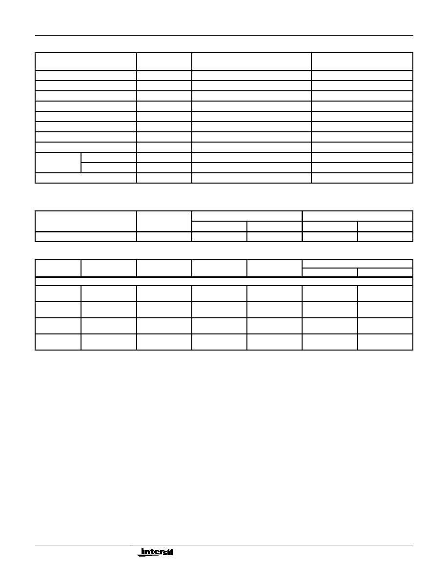
TABLE 4. POST IRRADIATION ELECTRICAL PERFORMANCE CHARACTERISTICS
PARAMETER
SYMBOL
CONDITIONS
NOTES
TEMPERATURE
LIMITS
UNITS
MIN
MAX
Supply Current
IDD
VDD = 20V, VIN = VDD or GND
1, 4
+25
o
C
-
25
µ
A
N Threshold Voltage
VTN
VDD = 10V, ISS = -10
µ
A
1, 4
+25
o
C
-2.8
-0.7
V
N Threshold Voltage
Delta
VTN
VDD = 10V, ISS = -10
µ
A
1, 4
+25
o
C
-
±
1
V
P Threshold Voltage
VTP
VSS = 0V, IDD = 10
µ
A
1, 4
+25
o
C
0.2
2.8
V
P Threshold Voltage
Delta
VTP
VSS = 0V, IDD = 10
µ
A
1, 4
+25
o
C
-
±
1
V
Functional
F
VDD = 18V, VIN = VDD or GND
1
+25
o
C
VOH >
VDD/2
VOL <
VDD/2
V
VDD = 3V, VIN = VDD or GND
Propagation Delay Time
TPHL
TPLH
VDD = 5V
1, 2, 3, 4
+25
o
C
-
1.35 x
+25
o
C
Limit
ns
NOTES: 1. All voltages referenced to device GND.
2. CL = 50pF, RL = 200K, Input TR, TF < 20ns.
3. See Table 2 for +25
o
C limit.
4. Read and Record
TABLE 5. BURN-IN AND LIFE TEST DELTA PARAMETERS +25
O
C
PARAMETER
SYMBOL
DELTA LIMIT
Supply Current - MSI-2
IDD
±
1.0
µ
A
Output Current (Sink)
IOL5
±
20% x Pre-Test Reading
Output Current (Source)
IOH5A
±
20% x Pre-Test Reading
TABLE 3. ELECTRICAL PERFORMANCE CHARACTERISTICS (Continued)
PARAMETER
SYMBOL
CONDITIONS
NOTES
TEMPERATURE
LIMITS
UNITS
MIN
MAX
CD4017BMS, CD4022BMS
5
TABLE 6. APPLICABLE SUBGROUPS
CONFORMANCE GROUP
MIL-STD-883
METHOD
GROUP A SUBGROUPS
READ AND RECORD
Initial Test (Pre Burn-In)
100% 5004
1, 7, 9
IDD, IOL5, IOH5A
Interim Test 1 (Post Burn-In)
100% 5004
1, 7, 9
IDD, IOL5, IOH5A
Interim Test 2 (Post Burn-In)
100% 5004
1, 7, 9
IDD, IOL5, IOH5A
PDA (Note 1)
100% 5004
1, 7, 9, Deltas
Interim Test 3 (Post Burn-In)
100% 5004
1, 7, 9
IDD, IOL5, IOH5A
PDA (Note 1)
100% 5004
1, 7, 9, Deltas
Final Test
100% 5004
2, 3, 8A, 8B, 10, 11
Group A
Sample 5005
1, 2, 3, 7, 8A, 8B, 9, 10, 11
Group B
Subgroup B-5
Sample 5005
1, 2, 3, 7, 8A, 8B, 9, 10, 11, Deltas
Subgroups 1, 2, 3, 9, 10, 11
Subgroup B-6
Sample 5005
1, 7, 9
Group D
Sample 5005
1, 2, 3, 8A, 8B, 9
Subgroups 1, 2 3
NOTE: 1. 5% Parameteric, 3% Functional; Cumulative for Static 1 and 2.
TABLE 7. TOTAL DOSE IRRADIATION
CONFORMANCE GROUPS
MIL-STD-883
METHOD
TEST
READ AND RECORD
PRE-IRRAD
POST-IRRAD
PRE-IRRAD
POST-IRRAD
Group E Subgroup 2
5005
1, 7, 9
Table 4
1, 9
Table 4
TABLE 8. BURN-IN AND IRRADIATION TEST CONNECTIONS
FUNCTION
OPEN
GROUND
VDD
9V
±
-0.5V
OSCILLATOR
50kHz
25kHz
PART NUMBER CD4017BMS AND CD4002B
Static Burn-In 1
Note 1
1 - 7, 9 - 12
8, 13, 15
14, 16
-
-
-
Static Burn-In 2
Note 1
1 - 7, 9 - 12
8, 14
13, 15, 16
-
-
-
Dynamic Burn-
In Note 1
-
8, 13, 15
16
1 - 7, 9 - 12
14
-
Irradiation
Note 2
1 - 7, 9 - 12
8
13 - 16
-
-
-
NOTE:
1. Each pin except VDD and GND will have a series resistor of 10K
±
5%, VDD = 18V
±
0.5V
2. Each pin except VDD and GND will have a series resistor of 47K
±
5%; Group E, Subgroup 2, sample size is 4 dice/wafer, 0 failures, VDD = 10V
±
0.5V
CD4017BMS, CD4022BMS