 | –≠–ª–µ–∫—Ç—Ä–æ–Ω–Ω—ã–π –∫–æ–º–ø–æ–Ω–µ–Ω—Ç: H1106I | –°–∫–∞—á–∞—Ç—å:  PDF PDF  ZIP ZIP |
Document Outline
- HFA1106
- A
- 25
- -
- 2
- 5
- mV
- A
- Full
- -
- 3
- 8
- mV
- B
- Full
- -
- 1
- 10
- mV/oC
- A
- 25
- 47
- 50
- -
- dB
- A
- 85
- 45
- 48
- -
- dB
- A
- -40
- 45
- 48
- -
- dB
- A
- 25
- 50
- 54
- -
- dB
- A
- 85
- 47
- 50
- -
- dB
- A
- -40
- 47
- 50
- -
- dB
- A
- 25
- -
- 6
- 15
- mA
- A
- Full
- -
- 10
- 25
- mA
- B
- Full
- -
- 5
- 60
- nA�/�oC
- A
- 25
- -
- 0.5
- 1
- mA/V
- A
- 85
- -
- 0.8
- 3
- mA/V
- A
- -40
- -
- 0.8
- 3
- mA/V
- A
- 25
- 0.8
- 1.2
- -
- MW
- A
- 85
- 0.5
- 0.8
- -
- MW
- A
- -40
- 0.5
- 0.8
- -
- MW
- A
- 25
- -
- 2
- 7.5
- mA
- A
- Full
- -
- 5
- 15
- mA
- B
- Full
- -
- 60
- 200
- nA�/�oC
- A
- 25
- -
- 3
- 6
- mA�/�V
- A
- 85
- -
- 4
- 8
- mA�/�V
- A
- -40
- -
- 4
- 8
- mA�/�V
- A
- 25
- -
- 2
- 5
- mA�/�V
- A
- 85
- -
- 4
- 8
- mA�/�V
- A
- -40
- -
- 4
- 8
- mA�/�V
- C
- 25
- -
- 60
- -
- W
- C
- 25
- -
- 1.6
- -
- pF
- A
- 25, 85
- ±1.8
- ±2.4
- -
- V
- A
- -40
- ±1.2
- ±1.7
- -
- V
- B
- 25
- -
- 3.5
- -
- nV/˜Hz
- B
- 25
- -
- 2.5
- -
- pA/˜Hz
- B
- 25
- -
- 20
- -
- pA/˜Hz
- C
- 25
- -
- 500
- -
- kW
- B
- 25
- 250
- 315
- -
- MHz
- B
- 25
- 140
- 170
- -
- MHz
- B
- 25
- 65
- 80
- -
- MHz
- B
- 25
- 185
- 245
- -
- MHz
- B
- 25
- 110
- 140
- -
- MHz
- B
- 25
- 55
- 70
- -
- MHz
- B
- 25
- 45
- 65
- -
- MHz
- B
- 25
- 25
- 40
- -
- MHz
- B
- 25
- 13
- 17
- -
- MHz
- B
- 25
- 60
- 100
- -
- MHz
- B
- 25
- 15
- 30
- -
- MHz
- B
- 25
- 11
- 14
- -
- MHz
- A
- Full
- 1
- -
- -
- V/�V
- A
- 25
- ±3
- ±3.4
- -
- V
- A
- Full
- ±2.8
- ±3
- -
- V
- A
- 25, 85
- 50
- 60
- -
- mA
- A
- -40
- 28
- 42
- -
- mA
- B
- 25
- -
- 0.07
- -
- W
- B
- 25
- -
- 90
- -
- mA
- B
- 25
- -45
- -53
- -
- dBc
- B
- 25
- -42
- -48
- -
- dBc
- B
- 25
- -38
- -44
- -
- dBc
- B
- 25
- -50
- -57
- -
- dBc
- B
- 25
- -48
- -56
- -
- dBc
- B
- 25
- -48
- -56
- -
- dBc
- B
- 25
- -42
- -46
- -
- dBc
- B
- 25
- -38
- -42
- -
- dBc
- B
- 25
- -34
- -38
- -
- dBc
- B
- 25
- -46
- -57
- -
- dBc
- B
- 25
- -52
- -57
- -
- dBc
- B
- 25
- -50
- -57
- -
- dBc
- B
- 25
- -
- 2.6
- 2.9
- ns
- B
- 25
- -
- 3.7
- 4.2
- ns
- B
- 25
- -
- 5.2
- 6.2
- ns
- B
- 25
- -
- 2.7
- 3.2
- ns
- B
- 25
- -
- 3.9
- 4.4
- ns
- B
- 25
- -
- 5.9
- 6.9
- ns
- B
- 25
- -
- 1.5
- 4
- %
- B
- 25
- -
- 6
- 10
- %
- B
- 25
- -
- 4
- 7.5
- %
- B
- 25
- -
- 2
- 5
- %
- B
- 25
- -
- 6.5
- 12
- %
- B
- 25
- -
- 2.5
- 7.5
- %
- B
- 25
- 580
- 680
- -
- V/ms
- B
- 25
- 400
- 545
- -
- V/ms
- B
- 25
- 470
- 530
- -
- V/ms
- B
- 25
- 300
- 410
- -
- V/ms
- B
- 25
- 320
- 365
- -
- V/ms
- B
- 25
- 200
- 300
- -
- V/ms
- B
- 25
- 750
- 910
- -
- V/ms
- B
- 25
- 500
- 720
- -
- V/ms
- B
- 25
- 550
- 730
- -
- V/ms
- B
- 25
- 350
- 520
- -
- V/ms
- B
- 25
- 380
- 485
- -
- V/ms
- B
- 25
- 250
- 375
- -
- V/ms
- B
- 25
- -
- 26
- 35
- ns
- B
- 25
- -
- 33
- 43
- ns
- B
- 25
- -
- 49
- 75
- ns
- B
- 25
- -
- 8.5
- -
- ns
- B
- 25
- -
- 0.02
- -
- %
- B
- 25
- -
- 0.02
- -
- %
- B
- 25
- -
- 0.05
- -
- Degrees
- B
- 25
- -
- 0.07
- -
- Degrees
- C
- 25
- ±4.5
- -
- ±5.5
- V
- A
- 25
- -
- 5.8
- 6.1
- mA
- A
- Full
- -
- 5.9
- 6.3
- mA
- Application Information
- PC Board Layout
- Evaluation Board
- Typical Performance Curves�VSUPPLY = ±5V, TA = 25oC, RL = 100W�, Unless Otherwise Specified��
- FIGURE 5.� SMALL SIGNAL PULSE RESPONSE
- FIGURE 6.� SMALL SIGNAL PULSE RESPONSE
- FIGURE 7.� LARGE SIGNAL PULSE RESPONSE
- FIGURE 8.� LARGE SIGNAL PULSE RESPONSE
- FIGURE 9.� LARGE SIGNAL PULSE RESPONSE
- FIGURE 10.� LARGE SIGNAL PULSE RESPONSE
- FIGURE 11.� FREQUENCY RESPONSE
- FIGURE 12.� GAIN FLATNESS
- FIGURE 13.� FREQUENCY RESPONSE (12 UNITS, 4 RUNS)
- FIGURE 14.� GAIN FLATNESS (12 UNITS, 4 RUNS)
- FIGURE 15.� FREQUENCY RESPONSE (12 UNITS, 4 RUNS)
- FIGURE 16.� GAIN FLATNESS (12 UNITS, 4 RUNS)
- FIGURE 17.� SMALL SIGNAL PULSE RESPONSE
- FIGURE 18.� SMALL SIGNAL PULSE RESPONSE
- FIGURE 19.� LARGE SIGNAL PULSE RESPONSE
- FIGURE 20.� LARGE SIGNAL OUTPUT VOLTAGE
- FIGURE 21.� LARGE SIGNAL PULSE RESPONSE
- FIGURE 22.� LARGE SIGNAL PULSE RESPONSE
- FIGURE 23.� FREQUENCY RESPONSE
- FIGURE 24.� GAIN FLATNESS
- FIGURE 25.� FREQUENCY RESPONSE (12 UNITS, 4 RUNS)
- FIGURE 26.� GAIN FLATNESS (12 UNITS, 4 RUNS)
- FIGURE 27.� FREQUENCY RESPONSE (12 UNITS, 4 RUNS)
- FIGURE 28.� GAIN FLATNESS (12 UNITS, 4 RUNS)
- FIGURE 29.� SMALL SIGNAL PULSE RESPONSE
- FIGURE 30.� SMALL SIGNAL PULSE RESPONSE
- FIGURE 31.� LARGE SIGNAL PULSE RESPONSE
- FIGURE 32.� LARGE SIGNAL PULSE RESPONSE
- FIGURE 33.� LARGE SIGNAL PULSE RESPONSE
- FIGURE 34.� LARGE SIGNAL PULSE RESPONSE
- FIGURE 35.� FREQUENCY RESPONSE
- FIGURE 36.� GAIN FLATNESS
- FIGURE 37.� FREQUENCY RESPONSE (12 UNITS, 4 RUNS)
- FIGURE 38.� GAIN FLATNESS (12 UNITS, 4 RUNS)
- FIGURE 39.� FREQUENCY RESPONSE (12 UNITS, 4 RUNS)
- FIGURE 40.� GAIN FLATNESS (12 UNITS, 4 RUNS)
- FIGURE 41.� SETTLING RESPONSE
- FIGURE 42.� OUTPUT VOLTAGE vs TEMPERATURE
- FIGURE 43.� SUPPLY CURRENT vs SUPPLY VOLTAGE
- Die Characteristics
- Metallization Mask Layout
- Part Number Information

3-28
Æ
September 1998
HFA1106
315MHz, Low Power, Video Operational
Amplifier with Compensation Pin
Features
∑ Compensation Pin for Bandwidth Limiting
∑ Lower Lot-to-Lot Variability With External
Compensation
∑ High Input Impedance . . . . . . . . . . . . . . . . . . . . . . . 1M
∑ Differential Gain . . . . . . . . . . . . . . . . . . . . . . . . . . 0.02%
∑ Differential Phase . . . . . . . . . . . . . . . . . . 0.05 Degrees
∑ Wide -3dB Bandwidth . . . . . . . . . . . . . . . . . . . . 315MHz
∑ Very Fast Slew Rate. . . . . . . . . . . . . . . . . . . . . . 700V/
µ
s
∑ Low Supply Current. . . . . . . . . . . . . . . . . . . . . . . 5.8mA
∑ Gain Flatness (to 100MHz) . . . . . . . . . . . . . . . . .
±
0.1dB
Applications
∑ Noise Critical Applications
∑ Professional Video Processing
∑ Medical Imaging
∑ Video Digitizing Boards/Systems
∑ Radar/IF Processing
∑ Hand Held and Miniaturized RF Equipment
∑ Battery Powered Communications
∑ Flash A/D Drivers
∑ Oscilloscopes and Analyzers
Description
The HFA1106 is a high speed, low power current feedback
operational amplifier built with Intersil's proprietary comple-
mentary bipolar UHF-1 process. This amplifier features a
compensation pin connected to the internal high impedance
node, which allows for implementation of external clamping
or bandwidth limiting.
Bandwidth limiting is accomplished by connecting a capaci-
tor (C
COMP
) and series damping resistor (R
COMP
) from pin
8 to ground. Amplifier performance for various values of
C
COMP
is documented in the Electrical Specifications.
The HFA1106 is ideal for noise critical wideband applica-
tions. Not only can the bandwidth be limited to minimize
broadband noise, the HFA1106 is optimized for lower feed-
back resistors (R
F
= 100
for A
V
= +2) than most current
feedback amplifiers. The low feedback resistor reduces the
inverting input noise current contribution to total output
noise, while reducing DC errors as well. Please see the
"Application Information" section for details.
Pinout
HFA1106
(PDIP, SOIC)
TOP VIEW
Part Number Information
PART NUMBER
(BRAND)
TEMP.
RANGE (
o
C)
PACKAGE
PKG.
NO.
HFA1106IP
-40 to 85
8 Ld PDIP
E8.3
HFA1106IB
(H1106I)
-40 to 85
8 Ld SOIC
M8.15
HFA11XXEVAL
DIP Evaluation Board for High Speed
Op Amps
NC
-IN
+IN
V-
1
2
3
4
8
7
6
5
COMP
V+
OUT
NC
+
-
CAUTION: These devices are sensitive to electrostatic discharge; follow proper IC Handling Procedures.
1-888-INTERSIL or 321-724-7143
|
Intersil (and design) is a registered trademark of Intersil Americas Inc.
Copyright © Intersil Americas Inc. 2002. All Rights Reserved
File Number
3922.2
OBS
OLE
TE P
ROD
UCT
REC
OMM
END
ED R
EPLA
CEM
ENT
HFA
1102
, HFA
1105
or co
ntac
t our
Tec
hnic
al Su
ppor
t Cen
ter a
t
1-88
8-INT
ERS
IL or
www
.inte
rsil.c
om/t
sc

3-29
Absolute Maximum Ratings
Thermal Information
Voltage Between V+ and V- . . . . . . . . . . . . . . . . . . . . . . . . . . . . 11V
DC Input Voltage . . . . . . . . . . . . . . . . . . . . . . . . . . . . . . . . V
SUPPLY
Differential Input Voltage . . . . . . . . . . . . . . . . . . . . . . . . . . . . . . . 8V
Output Current (Note 1) . . . . . . . . . . . . . . . . Short Circuit Protected
30mA Continuous
60mA
50% Duty Cycle
ESD Rating. . . . . . . . . . . . . . . . . . . . . . . . . . . . . . . . . . . . . . . >600V
Operating Conditions
Temperature Range . . . . . . . . . . . . . . . . . . . . . . . . . -40
o
C to 85
o
C
Thermal Resistance (Typical, Note 2)
JA
(
o
C/W)
PDIP Package . . . . . . . . . . . . . . . . . . . . . . . . . . . . . . .
130
SOIC Package. . . . . . . . . . . . . . . . . . . . . . . . . . . . . . .
170
Maximum Junction Temperature (Die Only) . . . . . . . . . . . . . . . 175
o
C
Maximum Junction Temperature (Plastic Package) . . . . . . . . 150
o
C
Maximum Storage Temperature Range . . . . . . . . . -65
o
C to 150
o
C
Maximum Lead Temperature (Soldering 10s). . . . . . . . . . . . 300
o
C
(SOIC - Lead Tips Only)
CAUTION: Stresses above those listed in "Absolute Maximum Ratings" may cause permanent damage to the device. This is a stress only rating and operation
of the device at these or any other conditions above those indicated in the operational sections of this specification is not implied.
NOTES:
1. Output is short circuit protected to ground. Brief short circuits to ground will not degrade reliability; however, continuous (100% duty cycle)
output current must not exceed 30mA for maximum reliability.
2.
JA
is measured with the component mounted on an evaluation PC board in free air.
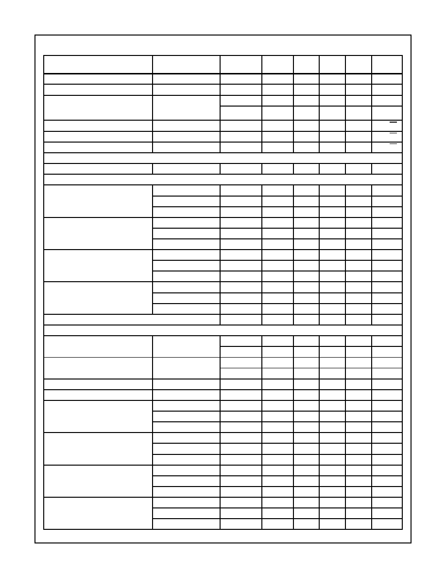
Electrical Specifications
V
SUPPLY
=
±
5V, A
V
= +1, R
F
= 510
, C
COMP
= 0pF, R
L
= 100
, Unless Otherwise Specified
PARAMETER
TEST CONDITIONS
(NOTE 3)
TEST LEVEL
TEMP.
(
o
C)
MIN
TYP
MAX
UNITS
INPUT CHARACTERISTICS
Input Offset Voltage
A
25
-
2
5
mV
A
Full
-
3
8
mV
Average Input Offset Voltage Drift
B
Full
-
1
10
µ
V/
o
C
Input Offset Voltage Common-Mode
Rejection Ratio
V
CM
=
±
1.8V
A
25
47
50
-
dB
V
CM
=
±
1.8V
A
85
45
48
-
dB
V
CM
=
±
1.2V
A
-40
45
48
-
dB
Input Offset Voltage Power Supply
Rejection Ratio
V
PS
=
±
1.8V
A
25
50
54
-
dB
V
PS
=
±
1.8V
A
85
47
50
-
dB
V
PS
=
±
1.2V
A
-40
47
50
-
dB
Non-Inverting Input Bias Current
A
25
-
6
15
µ
A
A
Full
-
10
25
µ
A
Non-Inverting Input Bias Current Drift
B
Full
-
5
60
nA/
o
C
Non-Inverting Input Bias Current
Power Supply Sensitivity
V
PS
=
±
1.8V
A
25
-
0.5
1
µ
A/V
V
PS
=
±
1.8V
A
85
-
0.8
3
µ
A/V
V
PS
=
±
1.2V
A
-40
-
0.8
3
µ
A/V
Non-Inverting Input Resistance
V
CM
=
±
1.8V
A
25
0.8
1.2
-
M
V
CM
=
±
1.8V
A
85
0.5
0.8
-
M
V
CM
=
±
1.2V
A
-40
0.5
0.8
-
M
Inverting Input Bias Current
A
25
-
2
7.5
µ
A
A
Full
-
5
15
µ
A
Inverting Input Bias Current Drift
B
Full
-
60
200
nA/
o
C
Inverting Input Bias Current
Common-Mode Sensitivity
V
CM
=
±
1.8V
A
25
-
3
6
µ
A/V
V
CM
=
±
1.8V
A
85
-
4
8
µ
A/V
V
CM
=
±
1.2V
A
-40
-
4
8
µ
A/V
Inverting Input Bias Current Power
Supply Sensitivity
V
PS
=
±
1.8V
A
25
-
2
5
µ
A/V
V
PS
=
±
1.8V
A
85
-
4
8
µ
A/V
V
PS
=
±
1.2V
A
-40
-
4
8
µ
A/V
HFA1106
3-30
Inverting Input Resistance
C
25
-
60
-
Input Capacitance
C
25
-
1.6
-
pF
Input Voltage Common Mode Range
(Implied by V
IO
CMRR, +R
IN
, and -I
BIAS
CMS Tests)
A
25, 85
±
1.8
±
2.4
-
V
A
-40
±
1.2
±
1.7
-
V
Input Noise Voltage Density
f = 100kHz
B
25
-
3.5
-
nV/
Hz
Non-Inverting Input Noise Current Density f = 100kHz
B
25
-
2.5
-
pA/
Hz
Inverting Input Noise Current Density
f = 100kHz
B
25
-
20
-
pA/
Hz
TRANSFER CHARACTERISTICS
Open Loop Transimpedance Gain
A
V
= -1
C
25
-
500
-
k
AC CHARACTERISTICS A
V
= +2, R
F
= 100
,
R
COMP
= 51
, Unless Otherwise Specified
-3dB Bandwidth
(A
V
= +1, R
F
= 150
, V
OUT
= 0.2V
P-P
)
C
C
= 0pF
B
25
250
315
-
MHz
C
C
= 2pF
B
25
140
170
-
MHz
C
C
= 5pF
B
25
65
80
-
MHz
-3dB Bandwidth
(A
V
= +2, V
OUT
= 0.2V
P-P
)
C
C
= 0pF
B
25
185
245
-
MHz
C
C
= 2pF
B
25
110
140
-
MHz
C
C
= 5pF
B
25
55
70
-
MHz
±
0.1dB Flat Bandwidth
(A
V
= +1, R
F
= 150
, V
OUT
= 0.2V
P-P
)
C
C
= 0pF
B
25
45
65
-
MHz
C
C
= 2pF
B
25
25
40
-
MHz
C
C
= 5pF
B
25
13
17
-
MHz
±
0.1dB Flat Bandwidth
(A
V
= +2, V
OUT
= 0.2V
P-P
)
C
C
= 0pF
B
25
60
100
-
MHz
C
C
= 2pF
B
25
15
30
-
MHz
C
C
= 5pF
B
25
11
14
-
MHz
Minimum Stable Gain
A
Full
1
-
-
V/V
OUTPUT CHARACTERISTICS A
V
= +2, R
F
= 100
, R
COMP
= 51
, Unless Otherwise Specified
Output Voltage Swing
A
V
= -1, R
F
= 510
A
25
±
3
±
3.4
-
V
A
Full
±
2.8
±
3
-
V
Output Current
A
V
= -1, R
L
= 50
,
R
F
= 510
A
25, 85
50
60
-
mA
A
-40
28
42
-
mA
Closed Loop Output Impedance
DC
B
25
-
0.07
-
Output Short Circuit Current
A
V
= -1
B
25
-
90
-
mA
Second Harmonic Distortion
(10MHz, V
OUT
= 2V
P-P
)
C
C
= 0pF
B
25
-45
-53
-
dBc
C
C
= 2pF
B
25
-42
-48
-
dBc
C
C
= 5pF
B
25
-38
-44
-
dBc
Third Harmonic Distortion
(10MHz, V
OUT
= 2V
P-P
)
C
C
= 0pF
B
25
-50
-57
-
dBc
C
C
= 2pF
B
25
-48
-56
-
dBc
C
C
= 5pF
B
25
-48
-56
-
dBc
Second Harmonic Distortion
(20MHz, V
OUT
= 2V
P-P
)
C
C
= 0pF
B
25
-42
-46
-
dBc
C
C
= 2pF
B
25
-38
-42
-
dBc
C
C
= 5pF
B
25
-34
-38
-
dBc
Third Harmonic Distortion
(20MHz, V
OUT
= 2V
P-P
)
C
C
= 0pF
B
25
-46
-57
-
dBc
C
C
= 2pF
B
25
-52
-57
-
dBc
C
C
= 5pF
B
25
-50
-57
-
dBc
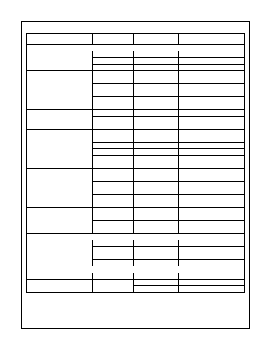
Electrical Specifications
V
SUPPLY
=
±
5V, A
V
= +1, R
F
= 510
, C
COMP
= 0pF, R
L
= 100
, Unless Otherwise Specified (Contin-
PARAMETER
TEST CONDITIONS
(NOTE 3)
TEST LEVEL
TEMP.
(
o
C)
MIN
TYP
MAX
UNITS
HFA1106
3-31
TRANSIENT CHARACTERISTICS A
V
= +2, R
F
= 100
, R
COMP
= 51
,
Unless Otherwise Specified
Rise and Fall Times
(V
OUT
= 0.5V
P-P
, A
V
= +1, R
F
= 150
)
C
C
= 0pF
B
25
-
2.6
2.9
ns
C
C
= 2pF
B
25
-
3.7
4.2
ns
C
C
= 5pF
B
25
-
5.2
6.2
ns
Rise and Fall Times
(V
OUT
= 0.5V
P-P
, A
V
= +2)
C
C
= 0pF
B
25
-
2.7
3.2
ns
C
C
= 2pF
B
25
-
3.9
4.4
ns
C
C
= 5pF
B
25
-
5.9
6.9
ns
Overshoot (Note 4)
(A
V
= +1, R
F
= 150
, V
IN
t
RISE
= 2.5ns)
V
OUT
= 250mV
P-P
B
25
-
1.5
4
%
V
OUT
= 2V
P-P
B
25
-
6
10
%
V
OUT
= 0V to 2V
B
25
-
4
7.5
%
Overshoot (Note 4)
(A
V
= +2, V
IN
t
RISE
= 2.5ns)
V
OUT
= 250mV
P-P
B
25
-
2
5
%
V
OUT
= 2V
P-P
B
25
-
6.5
12
%
V
OUT
= 0V to 2V
B
25
-
2.5
7.5
%
Slew Rate
(V
OUT
= 4V
P-P
, A
V
= +1, R
F
= 150
)
+SR, C
C
= 0pF
B
25
580
680
-
V/
µ
s
-SR, C
C
= 0pF
B
25
400
545
-
V/
µ
s
+SR, C
C
= 2pF
B
25
470
530
-
V/
µ
s
-SR, C
C
= 2pF
B
25
300
410
-
V/
µ
s
+SR, C
C
= 5pF
B
25
320
365
-
V/
µ
s
-SR, C
C
= 5pF
B
25
200
300
-
V/
µ
s
Slew Rate
(V
OUT
= 5V
P-P
, A
V
= +2)
+SR, C
C
= 0pF
B
25
750
910
-
V/
µ
s
-SR, C
C
= 0pF
B
25
500
720
-
V/
µ
s
+SR, C
C
= 2pF
B
25
550
730
-
V/
µ
s
-SR, C
C
= 2pF
B
25
350
520
-
V/
µ
s
+SR, C
C
= 5pF
B
25
380
485
-
V/
µ
s
-SR, C
C
= 5pF
B
25
250
375
-
V/
µ
s
Settling Time
(V
OUT
= +2V to 0V Step,
C
C
= 0pF to 5pF)
To 0.1%
B
25
-
26
35
ns
To 0.05%
B
25
-
33
43
ns
To 0.02%
B
25
-
49
75
ns
Overdrive Recovery Time
V
IN
=
±
2V
B
25
-
8.5
-
ns
VIDEO CHARACTERISTICS A
V
= +2, R
F
= 100
, R
COMP
= 51
,
Unless Otherwise Specified
Differential Gain
(f = 3.58MHz, R
L
= 150
)
C
C
= 0pF
B
25
-
0.02
-
%
C
C
= 5pF
B
25
-
0.02
-
%
Differential Phase
(f = 3.58MHz, R
L
= 150
)
C
C
= 0pF
B
25
-
0.05
-
Degrees
C
C
= 5pF
B
25
-
0.07
-
Degrees
POWER SUPPLY CHARACTERISTICS
Power Supply Range
C
25
±
4.5
-
±
5.5
V
Power Supply Current
A
25
-
5.8
6.1
mA
A
Full
-
5.9
6.3
mA
NOTES:
3. Test Level: A. Production Tested; B. Typical or Guaranteed Limit Based on Characterization; C. Design Typical for Information Only.
4. Undershoot dominates for output signal swings below GND (e.g. 2V
P-P
) yielding a higher overshoot limit compared to the V
OUT
= 0V to
2V condition.
Electrical Specifications
V
SUPPLY
=
±
5V, A
V
= +1, R
F
= 510
, C
COMP
= 0pF, R
L
= 100
, Unless Otherwise Specified (Contin-
PARAMETER
TEST CONDITIONS
(NOTE 3)
TEST LEVEL
TEMP.
(
o
C)
MIN
TYP
MAX
UNITS
HFA1106

3-32
Application Information
Optimum Feedback Resistor
All current feedback amplifiers (CFAs) require a feedback
resistor (R
F
) even for unity gain applications, and R
F
in
conjunction with the internal compensation capacitor sets
the dominant pole of the frequency response. Thus the
amplifier's bandwidth is inversely proportional to R
F
. The
HFA1106 design is optimized for R
F
= 150
at a gain of +1.
Decreasing R
F
decreases stability resulting in excessive
peaking and overshoot - Note: Capacitive feedback causes
the same problems due to the feedback impedance
decrease at higher frequencies. At higher gains, however,
the amplifier is more stable, so R
F
can be decreased in a
trade-off of stability for bandwidth (e.g., R
F
= 100
for
A
V
= +2).
Why Use Externally Compensated Amplifiers?
Externally compensated op amps were originally developed
to allow operation at gains below the amplifier's minimum
stable gain. This enabled development of non-unity gain sta-
ble op amps with very high bandwidth and slew rates. Users
needing lower closed loop gains could stabilize the amplifier
with external compensation if the associated performance
decrease was tolerable.
With the advent of CFAs, unity gain stability and high perfor-
mance are no longer mutually exclusive, so why offer unity
gain stable op amps with compensation pins?
The main reason for external compensation is to allow users
to tailor the amplifier's performance to their specific system
needs. Bandwidth can be limited to the exact value required,
thereby eliminating excess bandwidth and its associated
noise. A compensated op amp is also more predictable;
lower lot-to-lot variation requires less system overdesign to
cover process variability. Finally, access to the internal high
impedance node allows users to implement external output
limiting or allows for stabilizing the amplifier when driving
large capacitive loads.
Noise Advantages - Uncompensated
The HFA1106 delivers lower broadband noise even without
an external compensation capacitor. Package capacitance
present at the Comp pin stabilizes the op amp, so lower
value feedback resistors can be used. A smaller value R
F
minimizes the noise voltage contribution of the amplifier's
inverting input noise current - I
NI
x R
F
, usually a large con-
tributor on CFAs - and minimizes the resistor's thermal noise
contribution (4KTR
F
). Figure 1 details the HFA1105 broad-
band noise performance in its recommended configuration
of A
V
= +2, and R
F
= 510
. Adding a Comp pin to the
HFA1105 (thereby creating the HFA1106) yields the 23%
noise reduction shown in Figure 2.
In both cases, the scope
bandwidth, 100MHz, limits the measurement range to pre-
vent amplifier bandwidth differences from affecting the
results.
Offset Advantage
An added advantage of the lower value R
F
is a smaller DC
output offset. The op amp's inverting input bias current (I
BI
)
flows through the feedback resistor and generates an offset
voltage error defined by:
Reducing R
F
reduces these errors.
Bandwidth Limiting
The HFA1106 bandwidth may be limited by connecting a
resistor, R
COMP
(required to damp the interaction between
the compensation capacitor and the package parasitics),
and capacitor, C
COMP
, in series from pin 8 to GND. Typical
performance characteristics for various C
COMP
values are
listed in the specification table. The HFA1106 is already
unity gain stable, so the main reason for limiting the band-
width is to reduce the broadband noise.
Noise Advantages - Compensated
System noise reduction is maximized by limiting the op amp to
the bandwidth required for the application. Noise increases as
the square root of the bandwidth increase (4x bandwidth
increase yields 2x noise increase), so eliminating excess
E
N
= 456
µ
V
RMS
FIGURE 1. HFA1105 NOISE PERFORMANCE, A
V
= +2,
R
F
= 510
E
N
= 350
µ
V
RMS
FIGURE 2. HFA1106 NOISE PERFORMANCE,
UNCOMPENSATED, A
V
= +2, R
F
= 100
V
E
I
BI
x R
F
=
and
;
V
OS
A
V
V
IO
±
(
)
V
E
±
=
HFA1106