 | –≠–ª–µ–∫—Ç—Ä–æ–Ω–Ω—ã–π –∫–æ–º–ø–æ–Ω–µ–Ω—Ç: 10ETS12S | –°–∫–∞—á–∞—Ç—å:  PDF PDF  ZIP ZIP |
Major Ratings and Characteristics
Characteristics
10ETS..
Units
I
F(AV)
Sinusoidal waveform
10
A
V
RRM
Range
800 to 1200
V
I
FSM
200
A
V
F
@
10 A, T
J
= 25∞C
1.1
V
T
J
- 40 to 150
∞C
Capacitive input filter T
A
= 55∞C, T
J
= 125∞C
12.0
16.0
A
common heatsink of 1∞C/ W
Output Current in Typical Applications
Applications
Single-phase Bridge
Three-phase Bridge
Units
INPUT RECTIFIER DIODE
SAFE
IR
Series
10ETS12, 10ETS12S
Bulletin I2121 rev. C 12/01
1
www.irf.com
TO-220AC
Package Outline
D
2
Pak (SMD-220)
Package Outline
Description/Features
The 10ETS.. rectifier SAFE
IR
series has been
optimized for very low forward voltage drop, with
moderate leakage. The glass passivation
technology used has reliable operation up to 150∞C
junction temperature.
Typical applications are in input rectification and
these products are designed to be used with
International Rectifier Switches and Output
Rectifiers which are available in identical package
outlines.
V
F
< 1V @ 10A
I
FSM
= 200A
V
RRM
800 to 1200V
2
10ETS.., 10ETS..S SAFE
IR
Series
Bulletin I2121 rev. C 12/01
www.irf.com
I
F(AV)
Max. Average Forward Current
10
A
@ T
C
= 105∞ C, 180∞ conduction half sine wave
I
FSM
Max. Peak One Cycle Non-Repetitive
170
10ms Sine pulse, rated V
RRM
applied
Surge Current
200
10ms Sine pulse, no voltage reapplied
I
2
t
Max. I
2
t for fusing
130
10ms Sine pulse, rated V
RRM
applied
145
10ms Sine pulse, no voltage reapplied
I
2
t
Max. I
2
t for fusing
1450
A
2
s
t = 0.1 to 10ms, no voltage reapplied
Part Number
V
RRM
, maximum
V
RSM
, maximum non repetitive
I
RRM
peak reverse voltage
peak reverse voltage
150∞C
V
V
mA
10ETS08, 10ETS08S
800
900
0.5
10ETS12, 10ETS12S
1200
1300
Voltage Ratings
T
J
Max. Junction Temperature Range
- 40 to 150
∞C
T
stg
Max. Storage Temperature Range
- 40 to 150
∞C
R
thJC
Max. Thermal Resistance Junction
2.5
∞C/W
DC operation
to Case
R
thJA
Max. Thermal Resistance Junction
62
∞C/W
to Ambient (PCB Mount)*
T
s
Soldering Temperature
240
∞C
wt
Approximate Weight
2 (0.07)
g (oz.)
Case Style
TO-220AC, D
2
Pak (SMD-220)
Thermal-Mechanical Specifications
Parameters
10ETS.. Units
Conditions
Absolute Maximum Ratings
Electrical Specifications
Parameters
10ETS..
Units
Conditions
A
A
2
s
V
FM
Max. Forward Voltage Drop
1.1
V
@ 10A, T
J
= 25∞C
r
t
Forward slope resistance
20
m
V
F(TO)
Threshold voltage
0.82
V
I
RM
Max. Reverse Leakage Current
0.05
T
J
= 25 ∞C
0.50
T
J
= 150 ∞C
Parameters
10ETS..
Units
Conditions
T
J
= 150∞C
V
R
= rated V
RRM
mA
* When mounted on 1" square (650mm
2
) PCB of FR-4 or G-10 material 4 oz (140µm) copper 40∞C/W
For recommended footprint and soldering techniques refer to application note #AN-994
3
Bulletin I2121 rev. C 12/01
10ETS.., 10ETS..S SAFE
IR
Series
www.irf.com
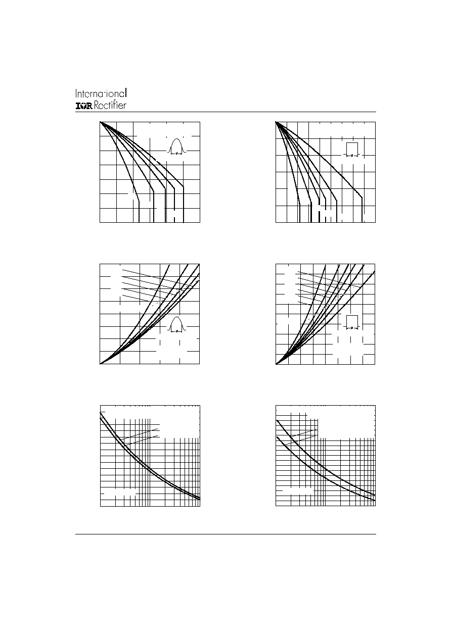
Fig. 1 - Current Rating Characteristics
Fig. 2 - Current Rating Characteristics
Fig. 3 - Forward Power Loss Characteristics
Fig. 4 - Forward Power Loss Characteristics
Fig. 5 - Maximum Non-Repetitive Surge Current
Fig. 6 - Maximum Non-Repetitive Surge Current
80
90
100
110
120
130
140
150
0
2
4
6
8
1 0
1 2
30
60
90
120
180
M
a
x
i
mu
m
A
l
l
o
wa
b
l
e
C
a
s
e
T
e
mp
e
r
a
t
u
r
e
(
C
)
C o n ductio n A ng le
A ve ra g e Fo rw a rd C urrent (A )
10ET S.. Se rie s
R (D C ) = 2.5 C /W
thJ C
90
100
110
120
130
140
150
0
2
4
6
8
10
12
14
16
18
D C
30
60
90
120
180
M
a
x
i
mu
m
A
l
l
o
w
a
b
l
e
C
a
s
e
T
e
mp
e
r
a
t
u
r
e
(
C
)
C ond uc tio n Perio d
A ve ra g e Forw a rd C urre n t (A)
10ETS.. Se ries
R (D C ) = 2.5 C / W
thJC
0
2
4
6
8
10
12
14
16
0
2
4
6
8
10
RM S Lim it
180
120
90
60
30
C o nd u ctio n Ang le
A ve rag e Fo rw a rd C urre n t (A )
M
a
xi
m
u
m
A
v
er
a
g
e F
o
r
w
a
r
d
P
o
w
e
r
L
o
s
s
(
W
)
10ET S.. Se rie s
T = 150 C
J
0
2
4
6
8
10
12
14
16
18
20
0
2
4
6
8
10
12
14
16
D C
180
120
90
60
30
RM S Lim it
C o nd uc tio n P erio d
A ve rag e Fo rw ard C u rre n t (A )
Ma
x
i
m
u
m
A
v
e
r
a
g
e
F
o
r
w
a
r
d
P
o
w
e
r
L
o
s
s
(
W
)
10E TS.. Se rie s
T = 150 C
J
40
60
80
100
120
140
160
180
200
1
10
100
N u m b er O f E q u al A m p litu d e Half C y cle Cu rren t Pu lses (N )
P
e
ak
Hal
f
S
i
n
e
W
a
v
e
F
o
r
w
ar
d C
u
r
r
e
n
t
(
A
)
In itia l T = 150 C
@ 60 H z 0.0083 s
@ 50 H z 0.0100 s
J
10E TS.. Se rie s
A t A n y Ra te d Lo a d C o n d ition A nd W ith
R a ted V A p p lie d Fo llo w ing Surg e .
RRM
40
60
80
100
120
140
160
180
200
220
240
0.01
0 .1
1
P u lse Tra in D u ra tio n (s)
P
e
ak
Hal
f
S
i
n
e
W
a
v
e
F
o
r
w
ar
d C
u
r
r
e
n
t
(
A
)
10ETS.. Se rie s
V e rsu s P u lse Tra in D u ra tio n .
M a xim um N o n R e p et it ive S urg e C urre n t
In itia l T = 150 C
N o V o ltag e R e ap plie d
Ra te d V R e ap p lie d
RR M
J
4
10ETS.., 10ETS..S SAFE
IR
Series
Bulletin I2121 rev. C 12/01
www.irf.com
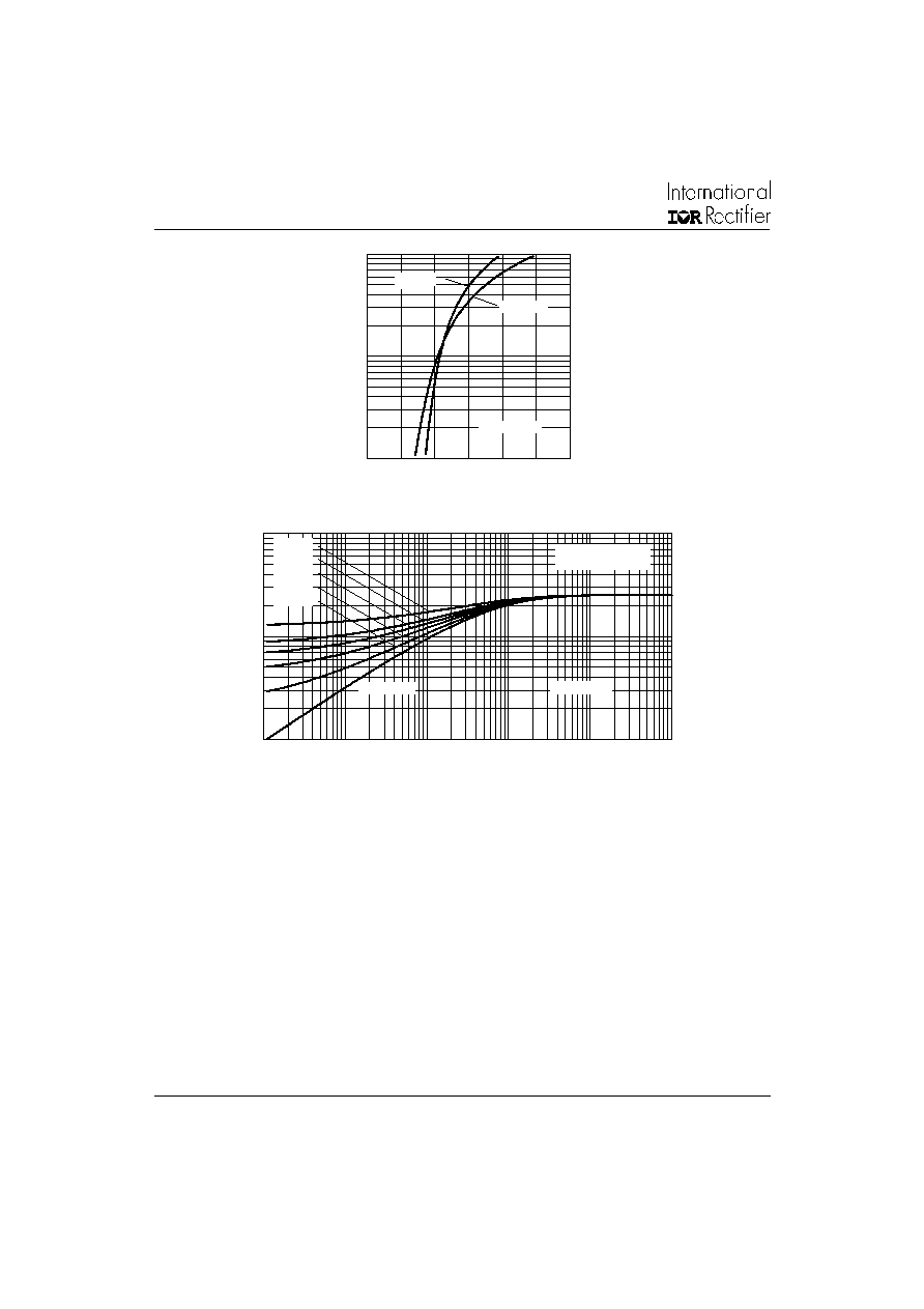
Fig. 9 - Thermal Impedance Z
thJC
Characteristics
Fig. 8 - Forward Voltage Drop Characteristics
0.1
1
10
0.0001
0.001
0.01
0.1
1
10
Square W ave P ulse D uratio n (s)
D = 0.50
D = 0.33
D = 0.25
D = 0.17
D = 0.08
Ste ad y State Value
(D C O pe ration )
10ETS.. Se ries
Sin g le Pulse
th
J
C
Tr
an
s
i
e
n
t
Th
e
r
m
a
l
I
m
p
e
d
a
n
c
e
Z
(
C
/
W
)
1
1 0
1 0 0
0
0.5
1
1.5
2
2.5
3
T = 25 C
J
I
n
st
a
n
t
a
n
e
o
u
s F
o
r
w
a
r
d
C
u
r
r
e
n
t
(A
)
In stan ta n e o us Fo rw a rd V o lta g e (V )
T = 150 C
J
10ETS.. Se rie s
5
Bulletin I2121 rev. C 12/01
10ETS.., 10ETS..S SAFE
IR
Series
www.irf.com
3.78 (0.15)
3.54 (0.14)
10.54 (0.41)
MAX.
DIA.
15.24 (0.60)
14.84 (0.58)
2.92 (0.11)
2.54 (0.10)
1
TERM 2
14.09 (0.55)
13.47 (0.53)
3.96 (0.16)
3.55 (0.14)
0.94 (0.04)
0.69 (0.03)
4.57 (0.18)
4.32 (0.17)
3
0.61 (0.02) MAX.
5.08 (0.20) REF.
1.32 (0.05)
1.22 (0.05)
6.48 (0.25)
6.23 (0.24)
2∞
0.10 (0.004)
1.40 (0.05)
1.15 (0.04)
2.89 (0.11)
2.64 (0.10)
1
3
2.04 (0.080) MAX.
2
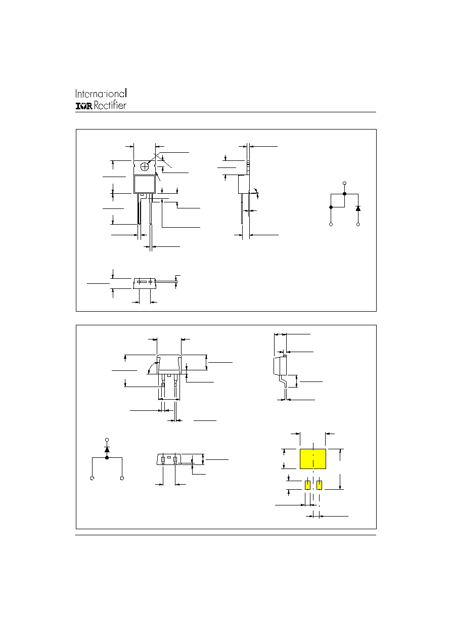
Outline Table
TO-220AC
Dimensions in millimeters (inches)
10.16 (0.40)
REF.
8.89 (0.35)
4.57 (0.18)
4.32 (0.17)
0.61 (0.02) MAX.
5.08 (0.20) REF.
1.32 (0.05)
1.22 (0.05)
1
3
6.47 (0.25)
6.18 (0.24)
93∞
REF.
2.61 (0.10)
2.32 (0.09)
5.28 (0.21)
4.78 (0.19)
4.69 (0.18)
4.20 (0.16)
0.55 (0.02)
0.46 (0.02)
14.73 (0.58)
15.49 (0.61)
1.40 (0.055)
1.14 (0.045)
3X
0.93 (0.37)
0.69 (0.27)
2X
11.43 (0.45)
17.78 (0.70)
8.89 (0.35)
3.81 (0.15)
2.08 (0.08)
2X
2.54 (0.10)
2X
MINIMUM RECOMMENDED FOOTPRINT
2
D
2
Pak (SMD-220)
Dimensions in millimeters and inches
Anode
1
3
Cathode
Base
Cathode
2
Anode
1
3
Base
Cathode
2
Anode