 | –≠–ª–µ–∫—Ç—Ä–æ–Ω–Ω—ã–π –∫–æ–º–ø–æ–Ω–µ–Ω—Ç: 150K40A | –°–∫–∞—á–∞—Ç—å:  PDF PDF  ZIP ZIP |
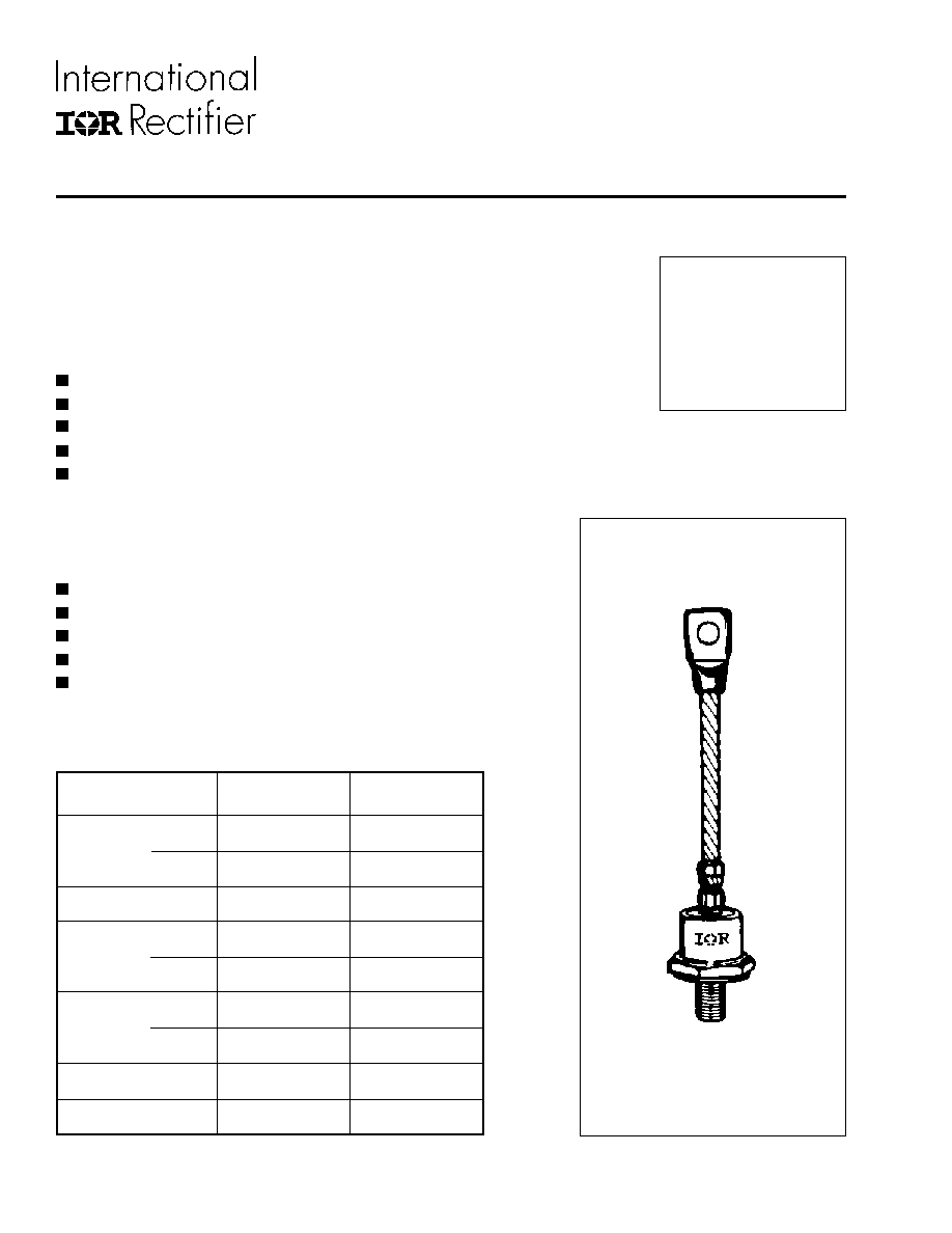
150A
STANDARD RECOVERY DIODES
Stud Version
SERIES
45L(R), 150K /L /KS(R)
Bulletin I2037
Features
Alloy diode
High current carrying capability
High voltage ratings up to 1000V
High surge current capabilities
Stud cathode and stud anode version
Typical Applications
Converters
Power supplies
Machine tool controls
High power drives
Medium traction applications
Major Ratings and Characteristics
I
F(AV)
150
A
@ T
C
150
∞C
I
F(RMS)
235
A
I
FSM
@
50Hz
3570
A
@ 60Hz
3740
A
I
2
t
@
50Hz
64
KA
2
s
@ 60Hz
58
KA
2
s
V
RRM
range *
50 to 1000
V
T
J
- 40 to 200
∞C
Parameters
45L /150...
Units
case style
DO-205AA (DO-8)
* 45L avaialble from 100V to 1000V
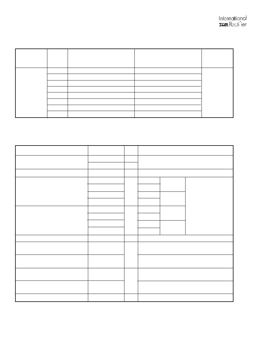
45L(R), 150K/ L/ KS(R) Series
Voltage
V
RRM
, maximum repetitive
V
RSM
, maximum non-
I
RRM
max.
Type number**
Code
peak reverse voltage
repetitive peak rev. voltage
@ T
J
= 175∞C
V
V
mA
5
50
100
35
10
100
200
35
20
200
300
35
30
300
400
35
40
400
500
35
60
600
720
35
80
800
960
32
100
1000
1200
24
ELECTRICAL SPECIFICATIONS
Voltage Ratings
45L(R) *
150K(R)
150L(R)
150KS(R)
* 45L 50V and 300V V
RRM
classes are not available.
**Also available as JEDEC series 1N3288A through 1N3296A (DO-8 case style) and 1N3111 through 1N3092 (DO-30 case style)
Forward Conduction
I
F(AV)
Max. average forward current
150
A
180∞ conduction, half sine wave
@ Case temperature
150
∞C
I
F(RMS)
Max. RMS forward current
235
A
DC @ 142∞C case temperature
I
FSM
Max. peak, one-cycle forward,
3570
t = 10ms
No voltage
non-repetitive surge current
3740
t = 8.3ms
reapplied
3000
t = 10ms
100% V
RRM
3140
t = 8.3ms
reapplied
Sinusoidal half wave,
I
2
t
Maximum I
2
t for fusing
64
t = 10ms
No voltage
Initial T
J
= T
J
max.
58
t = 8.3ms
reapplied
45
t = 10ms
100% V
RRM
41
t = 8.3ms
reapplied
I
2
t
Maximum I
2
t for fusing
640
KA
2
s
t = 0.1 to 10ms, no voltage reapplied
V
F(TO)1
Low level value of threshold
voltage
V
F(TO)2
High level value of threshold
voltage
r
f
1
Low level value of forward
slope resistance
r
f
2
High level value of forward
slope resistance
V
FM
Max. forward voltage drop
1.33
V
I
pk
= 471A, T
J
= 25∞C, t
p
= 10ms sinusoidal wave
Parameter
45L /150...
Units
Conditions
KA
2
s
A
V
m
0.67
(16.7% x
x I
F(AV)
< I <
x I
F(AV)
), T
J
= T
J
max.
0.83
(I > x
x I
F(AV)
),T
J
= T
J
max.
1.42
(16.7% x
x I
F(AV)
< I <
x I
F(AV)
), T
J
= T
J
max.
0.91
(I > x
x I
F(AV)
),T
J
= T
J
max.
45L(R), 150K/ L/ KS(R) Series
Parameter
45L /150...
Units
Conditions
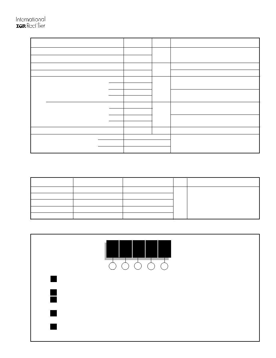
Thermal and Mechanical Specifications
∞C
K/W
T
J
Max. junction operating temperature
-40 to 200
T
stg
Max. storage temperature range
-40 to 200
R
thJC
Max. thermal resistance, junction to case
0.25
DC operation
R
thCS
Max. thermal resistance, case to heatsink
0.10
Mounting surface, smooth, flat and greased
T
Mounting torque
Min.
14.1 (125)
45L
Max.
17.0 (150)
150L
Min.
12.2 (108)
Max.
15.0 (132)
150K
Min.
11.3 (100)
150KS
Max.
14.1 (125)
Min.
9.5 (85)
Max.
12.5 (110)
wt
Approximate weight
100 (3.5)
g (oz)
150K-A
DO205AA (DO-8)
Case style
150KS
B-42
See Outline Table
150L-A/45L
DO-205AC (DO-30)
Nm
(lbf-in)
Not lubricated threads
Lubricated threads
Nm
(lbf-in)
Not lubricated threads
Lubricated threads
R
thJC
Conduction
(The following table shows the increment of thermal resistence R
thJC
when devices operate at different conduction angles than DC)
180∞
0.031
0.023
T
J
= T
J
max.
120∞
0.038
0.040
90∞
0.048
0.053
60∞
0.071
0.075
30∞
0.120
0.121
Conduction angle
Sinusoidal conduction
Rectangular conduction Units
Conditions
K/W
Ordering Information Table
45
L
F
R
100
1
2
3
4
5
Device Code
1
-
45
= Standard version
47
= Version with Pinch Bolt (only flat base; available on request)
2
-
L
= Essential Part Number
3
-
F
= Flat Base
None = Normal Stud 1/2" - 20UNF -2A
4
-
R
= Stud Reverse Polarity (Anode to Stud)
None = Stud Normal Polarity (Cathode to Stud)
5
-
Voltage code: Code x 10 = V
RRM
(See Voltage Ratings table)
NOTE: For longer lead Contact Factory
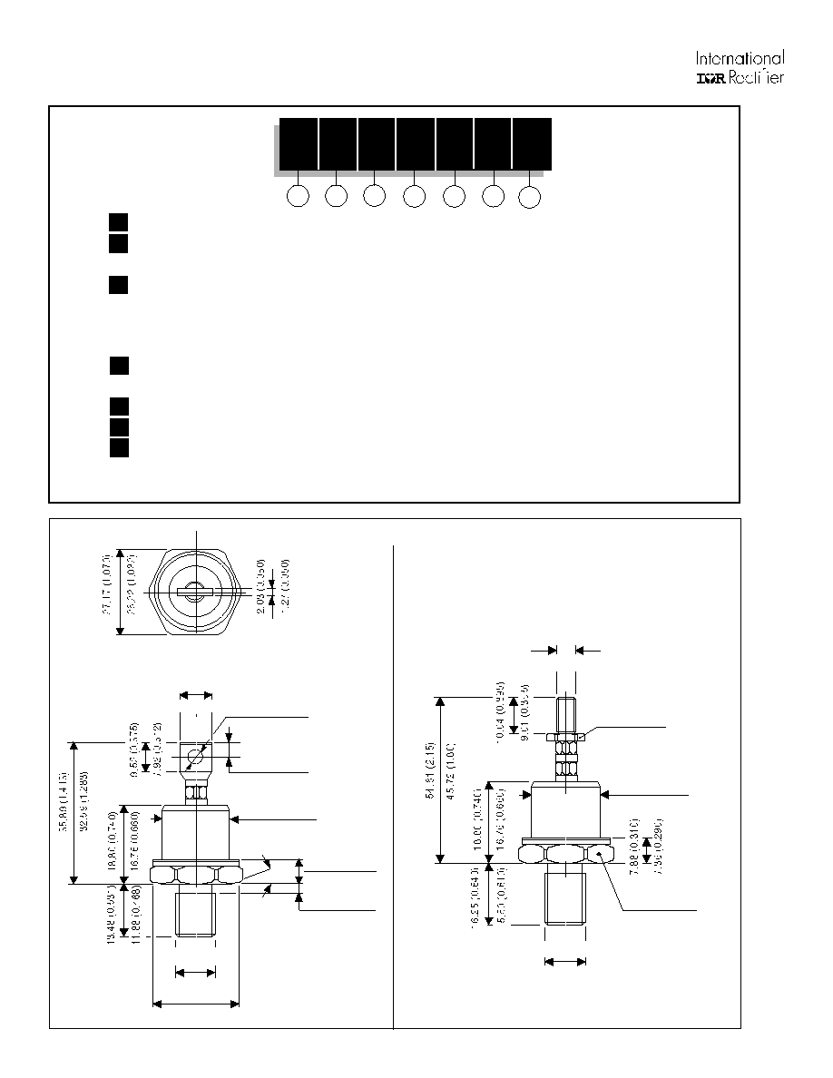
45L(R), 150K/ L/ KS(R) Series
Ordering Information Table
152K-A
IR Case Style B-28
150KS
Case Style B-42
All dimensions in millimeters (inches)
7.88 (0.310)
7.36 (0.290)
21.47 (0.843)
21.20 (0.835)
DIA.
9.52 (0.375)
7.87 (0.310)
15∞
4.08 (0.161)
3.84 (0.151)
4.34 (0.171)
4.09 (0.161)
DIA.
9.90 (0.390)
8.38 (0.330)
3/8"-24UNF-2A
26.04 (1.025)
MIN. BREAK DIA.
21.47 (0.843)
21.20 (0.835)
DIA.
3/8"-24UNF-2A
26.92 (1.06)
26.67 (1.05)
ACROSS FLATS
ACROSS FLATS
9.91 (0.390)
9.14 (0.360)
6.32 (0.249) MAX. DIA.
1/4"-28UNF-2A
1
-
Average Forward Current: Code x 10 = I
FAV
2
-
0
= Standard Case
2
= Stud Topped Case (152K-A only)
3
-
Case Style
K
= DO205AA (DO-8)
KS
= B-42
L
= DO205AC (DO-30)
4
-
R
= Stud Reverse Polarity (Anode to Stud)
None = Stud Normal Polarity (Cathode to Stud)
5
-
Voltage code: Code x 10 = V
RRM
(See Voltage Ratings table)
6
-
A
= Essential Part Number for 150K and 150L (Omitted for 150KS)
7
-
None = Standard Base
M
= Metric Base M12 x 1.5
NOTE: For longer lead Contact Factory
15
0
K
R
100
A
M
1
2
3
4
5
Device Code
6
7
45L(R), 150K/ L/ KS(R) Series
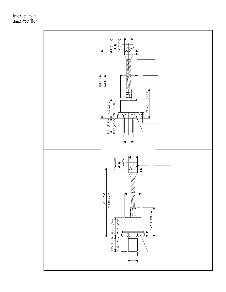
Outline Table
All dimensions in millimeters (inches)
45L
Case Style
150K
Case Style
21.47 (0.843)
21.20 (0.835)
1/2"-20UNF-2A
DIA.
7.39 (0.291)
6.89 (0.271)
15.24 (0.60)
12.70 (0.50)
10.41 (0.410)
8.90 (0.350)
7.88 (0.310)
7.36 (0.290)
26.92 (1.06)
26.67 (1.05)
ACROSS FLATS
DIA.
21.47 (0.843)
21.20 (0.835)
3/8"-24UNF-2A *
DIA.
7.39 (0.291)
6.89 (0.271)
15.24 (0.60)
12.70 (0.50)
10.41 (0.410)
8.90 (0.350)
7.88 (0.310)
7.36 (0.290)
26.92 (1.06)
26.67 (1.05)
ACROSS FLATS
* FOR METRIC DEVICE M12 X 1.5
DIA.