Major Ratings and Characteristics
I
F(AV)
Sinusoidal
waveform
V
RRM
800 to 1200
V
I
FSM
300
A
V
F
@
10 A, T
J
= 25∞C
1.0
V
T
J
- 40 to 150
∞C
Characteristics
20ETS..
Units
20
A
Output Current in Typical Applications
Single-phase Bridge
Three-phase Bridge
Units
Description/Features
The 20ETS.. rectifier SAFE
IR
series has been
optimized for very low forward voltage drop, with
moderate leakage. The glass passivation
technology used has reliable operation up to 150∞C
junction temperature.
Typical applications are in input rectification and
these products are designed to be used with
International Rectifier Switches and Output
Rectifiers which are available in identical package
outlines.
Capacitive input filter T
A
= 55∞C, T
J
= 125∞C,
16.3
21
A
common heatsink of 1∞C/W
INPUT RECTIFIER DIODE
V
F
< 1V @ 10A
I
FSM
= 300A
V
RRM
800 to 1200V
SAFE
IR
Series
20ETS12, 20ETS12S
1
Bulletin I2101 rev. D 12/01
Range (*)
TO-220AC
Package Outline
D
2
Pak (SMD-220)
Package Outline
www.irf.com
www.irf.com
20ETS.., 20ETS..S SAFE
IR
Series
Bulletin I2101 rev. D 12/01
2
Voltage Ratings
Part Number
V
RRM
, maximum
V
RSM
, maximum non repetitive
I
RRM
peak reverse voltage
peak reverse voltage
150∞C
V
V
mA
20ETS08, 20ETS08S
800
900
1
20ETS12, 20ETS12S
1200
1300
T
J
Max. Junction Temperature Range
- 40 to 150
∞C
T
stg
Max. Storage Temperature Range
- 40 to 150
∞C
R
thJC
Max. Thermal Resistance Junction
1.3
∞C/W
DC operation
to Case
R
thJA
Max. Thermal Resistance Junction
62
∞C/W
(*) For D
2
Pak version
to Ambient
R
thCS
Typ. Thermal Resistance Case
0.5
∞C/W
Mounting surface, smooth and greased
to Heatsink
wt
Approximate Weight
2 (0.07)
g (oz.)
T
Mounting Torque
Min.
6 (5)
Max.
12 (10)
Case Style
TO-220AC, D
2
Pak (SMD-220)
Thermal-Mechanical Specifications
Parameters
20ETS..
Units
Conditions
Kg-cm
(Ibf-in)
I
F(AV)
Max. Average Forward Current
20
A
@ T
C
= 105∞ C, 180∞ conduction half sine wave
I
FSM
Max. Peak One Cycle Non-Repetitive
250
10ms Sine pulse, rated V
RRM
applied
Surge Current
300
10ms Sine pulse, no voltage reapplied
I
2
t
Max. I
2
t for fusing
316
10ms Sine pulse, rated V
RRM
applied
442
10ms Sine pulse, no voltage reapplied
I
2
t
Max. I
2
t for fusing
4420
A
2
s
t = 0.1 to 10ms, no voltage reapplied
Absolute Maximum Ratings
Parameters
20ETS..
Units
Conditions
A
A
2
s
Electrical Specifications
V
FM
Max. Forward Voltage Drop
1.1
V
@ 20A, T
J
= 25∞C
r
t
Forward slope resistance
10.4
m
V
F(TO)
Threshold voltage
0.85
V
I
RM
Max. Reverse Leakage Current
0.1
T
J
= 25 ∞C
1.0
T
J
= 150 ∞C
Parameters
20ETS..
Units
Conditions
T
J
= 150∞C
V
R
= rated V
RRM
mA
* When mounted on 1" square (650mm
2
) PCB of FR-4 or G-10 material 4 oz (140µm) copper 40∞C/W
For recommended footprint and soldering techniques refer to application note # AN-994
3
20ETS.., 20ETS..S SAFE
IR
Series
Bulletin I2101 rev. D 12/01
www.irf.com
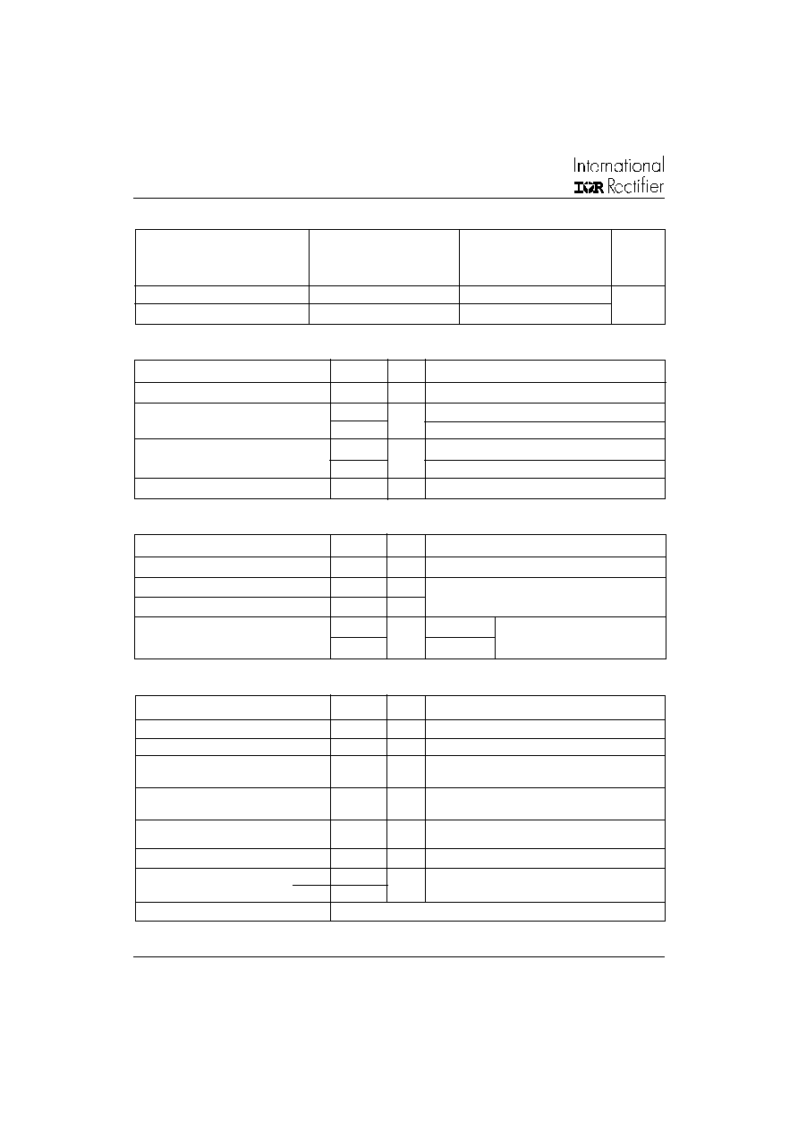
Fig. 1 - Current Rating Characteristics
Fig. 2 - Current Rating Characteristics
Fig. 4 - Forward Power Loss Characteristics
Fig. 3 - Forward Power Loss Characteristics
9 0
1 0 0
1 1 0
1 2 0
1 3 0
1 4 0
1 5 0
0
2
4
6
8
1 0 1 2 1 4 1 6 1 8 2 0 2 2
30
60
90 120
180
M
a
x
i
mu
m A
l
l
o
wa
b
l
e C
a
s
e
T
e
mp
e
r
a
t
ur
e
(
C
)
C ond uction A n gle
A vera g e Fo rw a rd C urrent (A )
20ETS.. Serie s
R (D C ) = 1.3 C /W
thJC
90
100
110
120
130
140
150
0
5
10
15
20
25
30
35
DC
30
60
90
120
180
M
a
x
i
mu
m
A
l
l
o
wa
b
l
e
C
a
s
e
T
e
mp
e
r
a
t
u
r
e
(
C
)
C ond uction Period
A ve ra g e Forw a rd C urre n t (A )
20ET S.. Se rie s
R (D C ) = 1.3 C / W
thJC
0
5
10
15
20
25
30
0
4
8
12
16
20
24
RM S Lim it
180
120
9 0
6 0
3 0
C ond uc tio n A n g le
M
a
x
i
m
u
m
A
v
e
r
a
g
e
F
o
rw
a
r
d
P
o
w
e
r L
o
s
s
(W
)
A ve ra g e Fo rw ard C urre n t (A )
20ET S.. Se rie s
T = 150 C
J
0
5
10
15
20
25
30
35
0
5
10
15
20
25
D C
180
120
90
60
30
A ve ra g e Fo rw a rd C urre n t (A )
RM S Lim it
M
a
x
i
m
u
m
A
v
er
a
g
e F
o
r
w
a
r
d
P
o
w
e
r
L
o
s
s
(
W
)
C ond uctio n P e rio d
20ETS.. Se rie s
T = 150 C
J
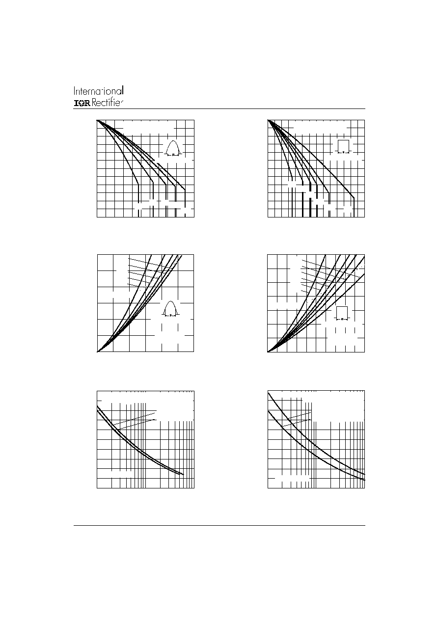
Fig. 5 - Maximum Non-Repetitive Surge Current
Fig. 6 - Maximum Non-Repetitive Surge Current
50
100
150
200
250
300
1
10
100
Nu m b er O f E q u a l A m p litu d e H a lf C y c le C u rre nt Pu lse s (N )
P
e
a
k
H
a
l
f
S
i
n
e
W
a
v
e
F
o
r
w
a
r
d
C
u
r
r
e
n
t
(
A
)
Initia l T = 150 C
@ 60 H z 0.0083 s
@ 50 H z 0.0100 s
J
A t A n y Ra te d Lo a d C on d itio n A nd W ith
R a ted V A p p lie d Fo llo w ing Su rg e .
RR M
2 0 E TS.. Se rie s
50
100
150
200
250
300
0.01
0.1
1
P u lse Tra in D ura tio n (s)
M a xim u m No n Rep etitiv e Su rge C urren t
P
e
ak
Ha
l
f
S
i
n
e
W
a
ve
F
o
r
w
a
r
d
C
u
r
r
e
n
t
(
A
)
Initia l T = 150 C
N o V olta g e Re a p p lied
Ra te d V R e a p p lie d
J
R RM
V ersus P ulse Tra in D ura tion.
2 0 E TS.. Se rie s
www.irf.com
20ETS.., 20ETS..S SAFE
IR
Series
Bulletin I2101 rev. D 12/01
4
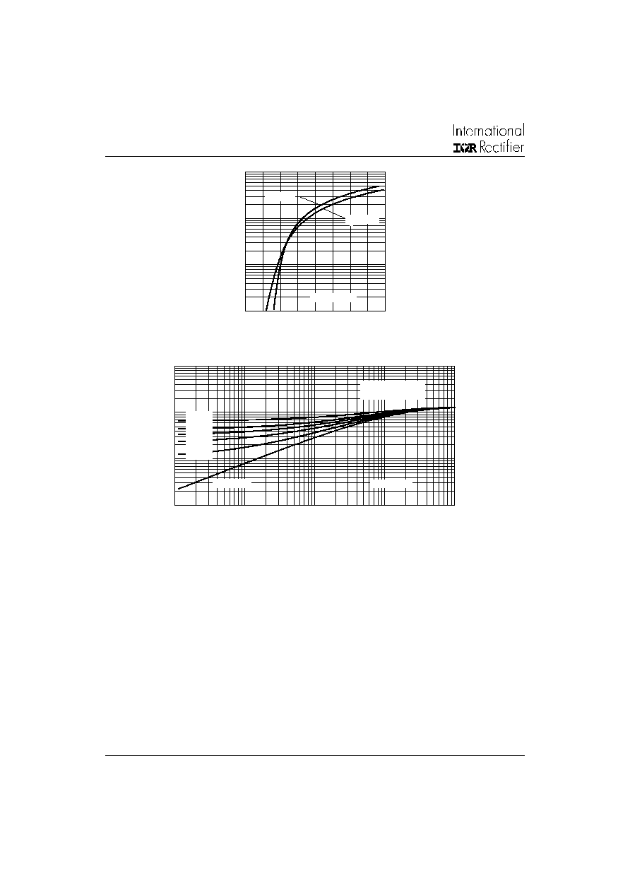
Fig. 8 - Thermal Impedance Z
thJC
Characteristics
Fig. 7 - Forward Voltage Drop Characteristics
1
10
100
1000
0
0.5
1
1.5
2
2.5
3
3.5
4
T = 25 C
J
I
n
s
t
an
t
a
n
e
o
u
s
F
o
r
w
ar
d C
u
r
r
e
n
t
(
A
)
In sta n ta n e o us F o rw a rd V o lta g e (V )
T = 150 C
J
20 ETS.. Series
0.0 1
0 .1
1
1 0
0.0 00 1
0 .00 1
0.0 1
0 .1
1
Sq uare W ave P ulse D uration (s)
th
J
C
Ste ady State V alue
(D C O p e ration )
Sin g le P ulse
D = 0.50
D = 0.33
D = 0.25
D = 0.17
D = 0.08
20ET S.. Se ries
Tr
a
n
si
e
n
t Th
e
r
m
a
l
I
m
p
e
d
a
n
c
e
Z
(
C
/
W
)
5
20ETS.., 20ETS..S SAFE
IR
Series
Bulletin I2101 rev. D 12/01
www.irf.com
3.78 (0.15)
3.54 (0.14)
10.54 (0.41)
MAX.
DIA.
15.24 (0.60)
14.84 (0.58)
2.92 (0.11)
2.54 (0.10)
1
TERM 2
14.09 (0.55)
13.47 (0.53)
3.96 (0.16)
3.55 (0.14)
0.94 (0.04)
0.69 (0.03)
4.57 (0.18)
4.32 (0.17)
3
0.61 (0.02) MAX.
5.08 (0.20) REF.
1.32 (0.05)
1.22 (0.05)
6.48 (0.25)
6.23 (0.24)
2∞
0.10 (0.004)
1.40 (0.05)
1.15 (0.04)
2.89 (0.11)
2.64 (0.10)
1
3
2.04 (0.080) MAX.
2
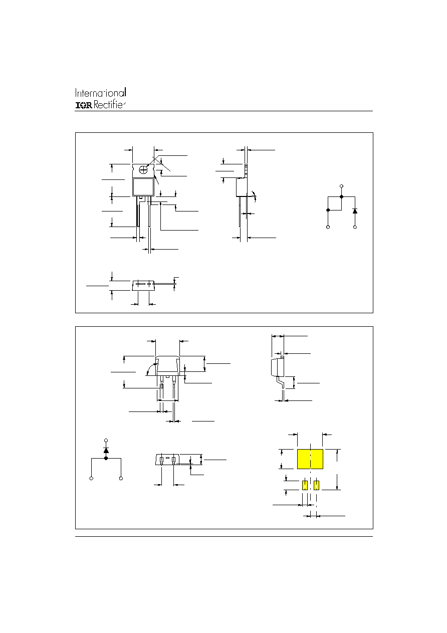
Outline Table
TO-220AC
Dimensions in millimeters (inches)
10.16 (0.40)
REF.
8.89 (0.35)
4.57 (0.18)
4.32 (0.17)
0.61 (0.02) MAX.
5.08 (0.20) REF.
1.32 (0.05)
1.22 (0.05)
1
3
6.47 (0.25)
6.18 (0.24)
93∞
REF.
2.61 (0.10)
2.32 (0.09)
5.28 (0.21)
4.78 (0.19)
4.69 (0.18)
4.20 (0.16)
0.55 (0.02)
0.46 (0.02)
14.73 (0.58)
15.49 (0.61)
1.40 (0.055)
1.14 (0.045)
3X
0.93 (0.37)
0.69 (0.27)
2X
11.43 (0.45)
17.78 (0.70)
8.89 (0.35)
3.81 (0.15)
2.08 (0.08)
2X
2.54 (0.10)
2X
MINIMUM RECOMMENDED FOOTPRINT
2
D
2
Pak (SMD-220)
Dimensions in millimeters and inches
Anode
1
3
Cathode
Base
Cathode
2
Anode
1
3
Base
Cathode
2
Anode