 | –≠–ª–µ–∫—Ç—Ä–æ–Ω–Ω—ã–π –∫–æ–º–ø–æ–Ω–µ–Ω—Ç: 26MB100A | –°–∫–∞—á–∞—Ç—å:  PDF PDF  ZIP ZIP |

Features
Universal, 3 way terminals:
push-on, wrap around or solder
High thermal conductivity package,
electrically insulated case
Center hole fixing
Excellent power/volume ratio
UL E 62320 approved
Nickel plated terminals solderable as per MIL-STD-202 Method
208; solder: Sn/Pb (60/40); solder temperature: 235-260∞C
max. time: 8-10 secs
Description
A range of extremely compact, encapsulated
single phase bridge rectifiers offering efficient and
reliable operation. They are intended for use in
general purpose and instrumentation applica-
tions.
Parameters 26MB-A
36MB-A
Units
Major Ratings and Characteristics
I
O
25
35
A
@ T
C
65
60
o
C
I
FSM
@
50Hz
400
475
A
@ 60Hz
420
500
A
I
2
t
@ 50Hz
790
1130
A
2
s
@ 60Hz
725
1030
A
2
s
V
RRM
range
200 to 1200
V
T
J
- 55 to 150
o
C
SINGLE PHASE BRIDGE
Power Modules
25 A
35 A
MB SERIES
Bulletin I2715 rev. I 03/03
1
www.irf.com

MB Series
2
Bulletin I2715 rev. I 03/03
www.irf.com
I
O
Maximum DC output current
25
35
A
Resistive or inductive load
20
28
A
Capacitive load
@ Case temperature
65
60
∞C
I
FSM
Maximum peak, one-cycle
400
475
A
t = 10ms
No voltage
non-repetitive forward current
420
500
t = 8.3ms
reapplied
335
400
t = 10ms
100% V
RRM
350
420
t = 8.3ms
reapplied
Initial T
J
= T
J
max.
I
2
t
Maximum I
2
t for fusing
790
1130
A
2
s
t = 10ms
No voltage
725
1030
t = 8.3ms
reapplied
560
800
t = 10ms
100% V
RRM
512
730
t = 8.3ms
reapplied
I
2
t
Maximum I
2
t for fusing
5.6
11.3
KA
2
s I
2
t for time t
x
= I
2
t x
t
x
;
0.1
t
x
10ms, V
RRM
= 0V
V
F(TO)1
Low-level of threshold voltage
0.76
0.79
V
(16.7% x
x I
F(AV)
< I <
x I
F(AV)
), @ T
J
max.
V
F(TO)2
High-level of threshold voltage
0.92
0.96
(I >
x I
F(AV)
), @ T
J
max.
r
t1
Low-level forward slope resistance
6.8
5.8
m
(16.7% x
x I
F(AV)
< I <
x I
F(AV)
), @ T
J
max.
r
t2
High-level forward slope resistance
5.0
4.5
(I >
x I
F(AV)
), @ T
J
max.
V
FM
Maximum forward voltage drop
1.11
1.14
V
T
J
= 25
o
C, I
FM
= 40A
PK
(26MB)
T
J
= 25
o
C, I
FM
= 55A
PK
(36MB)
I
RRM
Max. DC reverse current
10
10
µ
A
T
J
= 25
o
C, per diode at V
RRM
V
INS
RMS isolation voltage base plate
2700
2700
V
f = 50 Hz, t = 1s
Forward Conduction
Voltage
V
RRM
, maximum repetitive
V
RSM
, maximum non-
I
RRM
max.
Type number
Code
peak reverse voltage
repetitive peak rev. voltage
@ T
J
max.
V
V
20
200
275
40
400
500
26MB..A
60
600
725
2
36MB..A
80
800
900
100
1000
1100
120
1200
1300
ELECTRICAL SPECIFICATIONS
Voltage Ratings
Parameters
26MB-A
36MB-A Units Conditions
tp = 400
µ
s

MB Series
3
Bulletin I2715 rev. I 03/03
www.irf.com
T
J
Junction temperature range
- 55 to 150
o
C
T
stg
Storage temperature range
- 55 to 150
o
C
R
thJC
Max. thermal resistance junction to case
1.7
1.2
K/W
Per bridge
R
thCS
Max. thermal resistance, case to heatsink
0.2
K/W
Mounting surface , smooth, flat and greased
wt
Approximate weight
20
g
T
Mounting Torque
±
10%
2.0
Nm
Bridge to heatsink
All dimensions in millimetres (inches)
Suggested plugging force:
200 N max; axially applied to faston terminals
26 = 25A (Avg)
36 = 35A (Avg)
1
-
Current rating code:
2
-
Circuit configuration:
MB = Single phase european coding
3
-
Voltage code: MB series = code x 10 = V
RRM
4
-
Diode bridge rectifier:
A = 26MB, 36MB Series
36
MB
120
A
1
2
3
4
Thermal and Mechanical Specifications
Ordering Information Table
Outline Table
Device Code
Parameters
26MB-A
36MB-A Units Conditions
Not To Scale
0.8 (.03)
6.3 (.25)
10.5 (.41)
20.3 (.80)

MB Series
4
Bulletin I2715 rev. I 03/03
www.irf.com
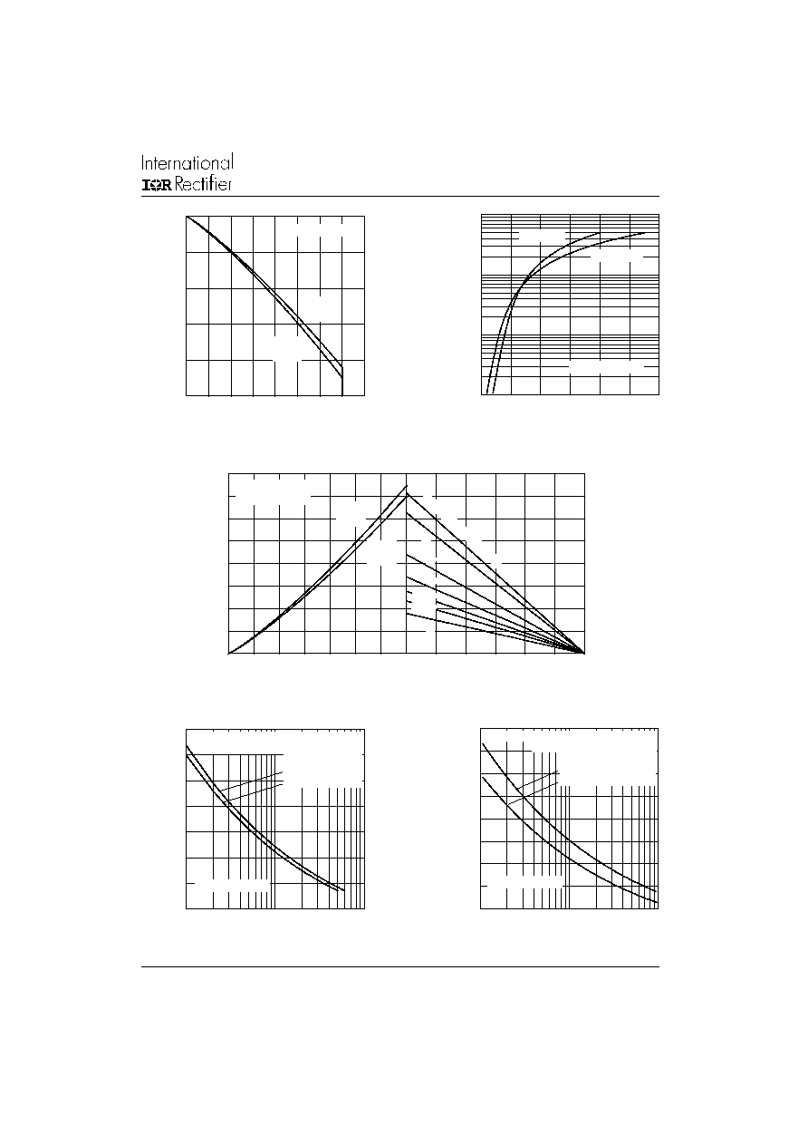
Fig. 1 - Current Ratings Characteristics
Fig. 2 - Forward Voltage Drop Characteristics
Fig. 4 - Maximum Non-Repetitive Surge Current
Fig. 5 - Maximum Non-Repetitive Surge Current
Average Forward Current (A)
Maximum Allowable Case temperature (∞C)
Instantaneous Forward Voltage (V)
Instantaneous Forward Current (A)
Maximum Allowable Ambient Te
50
70
90
110
130
150
0
5
10
15
20
25
30
180∞
(Rect)
180∞
(Sine)
26MB..A Series
1
10
100
1000
0.5
1
1.5
2
2.5
3
3.5
26MB..A Series
Tj = 25∞C
Tj = 150∞C
Number of Equal Amplitude Half Cycle Current Pulses (N)
Peak Half Sine Wave Forward Current (A)
50
150
250
350
450
0.01
0.1
1
Maximum Non Repetitive Surge Current
Versus Pulse Train Duration.
26MB..A Series
Initial Tj = 150∞C
No Voltage Reapplied
Rated Vrrm Reapplied
Peak Half Sine Wave Forward Current (A)
Pulse Train Duration (s)
100
150
200
250
300
350
400
1
10
100
26MB..A series
At Any Rated Load Condition And With
Initial Tj = 150∞C
@ 60 Hz 0.0083 s
@ 50 Hz 0.0100 s
Rated Vrrm Applied Following Surge
Fig. 3 - Total Power Loss Characteristics
Average Forward Current (A)
Maximum Allowable Ambient Temperature (∞C)
0
10
20
30
40
50
0
5
10
15
20
25
180∞
(Sine)
26MB..A Series
Tj = 150∞C
180∞
(Rect)
0
25
50
75
100
125
150
2 K/W
3 K/W
4 K/W
5 K/W
7 K/W
10 K/W
RthSA = 1 K/W - Delta R
Maximum Average Forward Power Loss (W)
MB Series
5
Bulletin I2715 rev. I 03/03
www.irf.com
Fig. 6 - Current Ratings Characteristics
Fig. 7 - Forward Voltage Drop Characteristics
Fig. 3 - Total Power Loss Characteristics
Fig. 9 - Maximum Non-Repetitive Surge Current
Fig. 10 - Maximum Non-Repetitive Surge Current
Average Forward Current (A)
Maximum Allowable Case temperature (
∞
C)
Instantaneous Forward Voltage (V)
Instantaneous Forward Current (A)
Maximum Allowable Ambient Te
Average Forward Current (A)
Maximum Average Forward Power Loss (W)
Maximum Allowable Ambient Temperature (∞C)
Number of Equal Amplitude Half Cycle Current Pulses (N)
Peak Half Sine Wave Forward Current (A)
Peak Half Sine Wave Forward Current (A)
Pulse Train Duration (s)
50
70
90
110
130
150
0
5
10
15
20
25
30
35
40
180∞
(Rect)
180∞
(Sine)
36MB..A Series
1
10
100
1000
0.5
1
1.5
2
2.5
3
3.5
Tj = 25∞C
Tj = 150∞C
36MB..A Series
0
25
50
75
100
125
150
1 K/W
2 K/W
3 K/W
4 K/W
5 K/W
7 K/W
RthSA = 0.7 K/W - Delta R
0
20
40
60
80
0
5
10
15
20
25
30
180∞
(Sine)
180∞
(Rect)
36MB..A Series
Tj = 150∞C
35
100
150
200
250
300
350
400
450
1
10
100
At Any Rated Load Condition And With
Rated Vrrm Applied Following Surge.
Initial Tj = 150∞C
@ 60 Hz 0.0083 s
@ 50 Hz 0.0100 s
36MB..A Series
100
150
200
250
300
350
400
450
500
0.01
0.1
1
Maximum Non Repetitive Surge Current
Versus Pulse Train Duration.
Initial Tj = 150∞C
No Voltage Reapplied
Rated Vrrm Reapplied
36MB..A Series
MB Series
6
Bulletin I2715 rev. I 03/03
www.irf.com
IR WORLD HEADQUARTERS: 233 Kansas St., El Segundo, California 90245, USA Tel: (310) 252-7105
TAC Fax: (310) 252-7309
Visit us at www.irf.com for sales contact information. 03/03
Data and specifications subject to change without notice.
This product has been designed and qualified for Industrial and Consumer Level.
Qualification Standards can be found on IR's Web site.