 | –≠–ª–µ–∫—Ç—Ä–æ–Ω–Ω—ã–π –∫–æ–º–ø–æ–Ω–µ–Ω—Ç: 70EPF10J | –°–∫–∞—á–∞—Ç—å:  PDF PDF  ZIP ZIP |

I
F(AV)
Rect. Conduction
50% duty Cycle
@ T
C
= 97∞ C
V
RRM
range (*)
1000/ 1200
V
I
FSM
950
A
V
F
@
70A, T
J
= 25∞C
1.45
V
t
rr
@ 100A/ µs, T
J
= 25∞C
100
ns
T
J
range
- 40 to 150
∞C
Characteristics
70EPF..
Units
70
A
Major Ratings and Characteristics
Description/Features
FAST SOFT RECOVERY
RECTIFIER DIODE
Bulletin I2155 rev. C 12/02
V
F
< 1.45V @ 70A
t
rr
= 100ns
V
RRM
1000/1200V
QUIET
IR
Series
70EPF..
(*)
for higher voltage up to 1600V contact factory
1
Case Styles
70EPF..
70EPF..J
The 70EPF.. fast soft recovery
QUIET
IR
rectifier series
has been optimized for combined short reverse recovery
time and low forward voltage drop.
The glass passivation ensures stable reliable operation in
the most severe temperature and power cycling conditions.
Available in the new Pow
IR
tab
TM
package, this new series
is suitable for a large range of applications combining
excellent die to footprint ratio and sturdeness connectivity
for use in high current environments.
Typical applications are both:
Output rectification and freewheeling in
inverters, choppers and converters
Input rectifications where severe
restrictions on conducted EMI should be met.
www.irf.com

2
70EPF..HV QUIET
IR
Series
Bulletin I2155 rev. C 12/02
www.irf.com
I
F(AV)
Max. Average Forward Current
70
A
@ T
C
= 93∞ C, 180∞ conduction half sine wave
I
FSM
Max. Peak One Cycle Non-Repetitive
800
A
10ms Sine pulse, rated V
RRM
applied
Surge Current
950
10ms Sine pulse, no voltage reapplied
I
2
t
Max. I
2
t for fusing
3200
A
2
s
10ms Sine pulse, rated V
RRM
applied
4500
10ms Sine pulse, no voltage reapplied
I
2
t
Max. I
2
t for fusing
32000
A
2
s
10ms, no voltage reapplied
V
RRM
, maximum
V
RSM
, maximum non repetitive
I
RRM
peak reverse voltage
peak reverse voltage
150∞C
V
V
mA
70EPF10
1000
1100
15
70EPF12
1200
1300
Voltage Ratings
Part Number
V
FM
Max. Forward Voltage Drop
1.45
V
@ 70A, T
J
= 25∞C
r
t
Forward slope resistance
4.13
m
V
F(TO)
Threshold voltage
0.94
V
I
R M
Max. Reverse Leakage Current
0.1
mA
T
J
= 25 ∞C
12
T
J
= 150 ∞C
Electrical Specifications
T
J
= 150∞C
V
R
= rated V
RRM
Absolute Maximum Ratings
Parameters
70EPF.. Units Conditions
Parameters
70EPF.. Units Conditions
Recovery Characteristics
t
rr
Reverse Recovery Time
500
ns
I
F
@ 85Apk
I
rr
Reverse Recovery Current
8.4
A
@ 25A/ µs
Q
rr
Reverse Recovery Charge
2.9
µC
@ 25∞C
S
Snap Factor
0.5
Parameters
70EPF.. Units
Conditions
3
70EPF..HV QUIET
IR
Series
Bulletin I2155 rev. C 12/02
www.irf.com
T
J
Max. Junction Temperature Range
- 40 to 150
∞C
T
stg
Max. Storage Temperature Range
- 40 to 150
∞C
R
thJC
Max. Thermal Resistance Junction
0.35
∞C/W
DC operation
to Case
R
thJA
Max. Thermal Resistance Junction
40
∞C/W
to Ambient
R
thCS
Typical Thermal Resistance, Case to
0.2
∞C/W
Mounting surface , smooth and greased
Heatsink
wt
Approximate Weight
6 (0.21)
g (oz.)
T
Mounting Torque
Min.
6 (5)
Max.
12 (10)
Case Style
PowIRtab
TM
Thermal-Mechanical Specifications
Parameters
70EPF.. Units Conditions
Kg-cm
(Ibf-in)
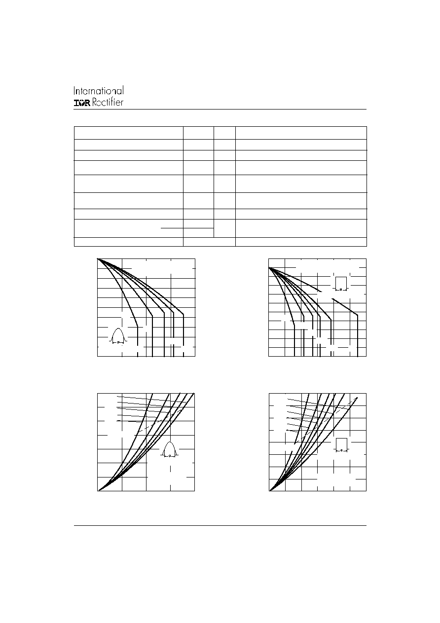
Fig. 1 - Current Rating Characteristics
Fig. 2 - Current Rating Characteristics
Fig. 3 - Forward Power Loss Characteristics
Fig. 4 - Forward Power Loss Characteristics
Average Forward Current (A)
Maximum Allowable Case Temperature (∞C)
Average Forward Current (A)
Maximum Allowable Case Temperature (∞C)
50
60
70
80
90
100
110
120
130
140
150
0
20
40
60
80
30∞
60∞
90∞
120∞
180∞
Conduction Angle
70EPF.. Series
R (DC) = 0.35 K/W
thJC
50
60
70
80
90
100
110
120
130
140
150
160
0
20
40
60
80
100
120
DC
60∞
90∞
30∞
120∞
180∞
Conduction Period
70EPF.. Series
R (DC) = 0.35 K/W
thJC
Average Forward Current (A)
Maximum Average Forward Power Loss (W)
Average Forward Current (A)
Maximum Average Forward Power Loss (W)
0
20
40
60
80
100
120
140
0
20
40
60
80
RMS Limit
180∞
120∞
90∞
60∞
30∞
Conduction Angle
70EPF.. Series
T = 150∞C
J
0
20
40
60
80
100
120
140
160
0
20
40
60
80
100
120
DC
180∞
120∞
90∞
60∞
30∞
RMS Limit
Conduction Period
70EPF.. Series
T = 150∞C
J
4
70EPF..HV QUIET
IR
Series
Bulletin I2155 rev. C 12/02
www.irf.com
Fig. 5 - Maximum Non-Repetitive Surge Current
Fig. 6 - Maximum Non-Repetitive Surge Current
Fig. 7 - Forward Voltage Drop Characteristics
Fig. 9 - Recovery Time Characteristics, T
J
= 150∞C
Fig. 8 - Recovery Time Characteristics, T
J
= 25∞C
100
200
300
400
500
600
700
800
900
1
10
100
At Any Rated Load Condition And With
Rated Vrrm Applied Following Surge.
Initial Tj = 150∞C
@ 60 Hz 0.0083 s
@ 50 Hz 0.0100 s
70EPF.. Series
Peak Half Wave Forward Current (A)
Number of Equal Amplitude Half Cycle Current Pulses (n)
Pulse Train Duration (s)
Peak Half Wave Forward Current (A)
100
200
300
400
500
600
700
800
900
1000
0.01
0.1
1
10
Versus Pulse Train Duration.
Maximum Non Repetitive Surge Current
Initial Tj = 150∞C
No Voltage Reapplied
Rated Vrrm Reapplied
70EPF.. Series
Instantaneous Forward Voltage (V)
Instantaneous Forward Current (A)
Rate Of Fall Of Forward Current - dI/dt (A/µs)
Maximum Reverse recovery Time - trr (µs)
Rate Of Fall Of Forward Current - dI/dt (A/µs)
Maximum Reverse recovery Time - trr (µs)
0
100
200
300
400
500
600
700
0
20
40
60
80
100
1 A
5 A
10 A
30 A
70EPF.. Series
T = 25∞C
J
I = 70 A
FM
100
200
300
400
500
600
700
800
900
1000
0
20
40
60
80
100
1 A
5 A
10 A
30 A
70EPF.. Series
T = 150∞C
J
I = 70 A
FM
1
10
100
1000
0
1
2
3
4
5
70EPF.. Series
T = 150∞C
J
T = 25∞C
J
5
70EPF..HV QUIET
IR
Series
Bulletin I2155 rev. C 12/02
www.irf.com
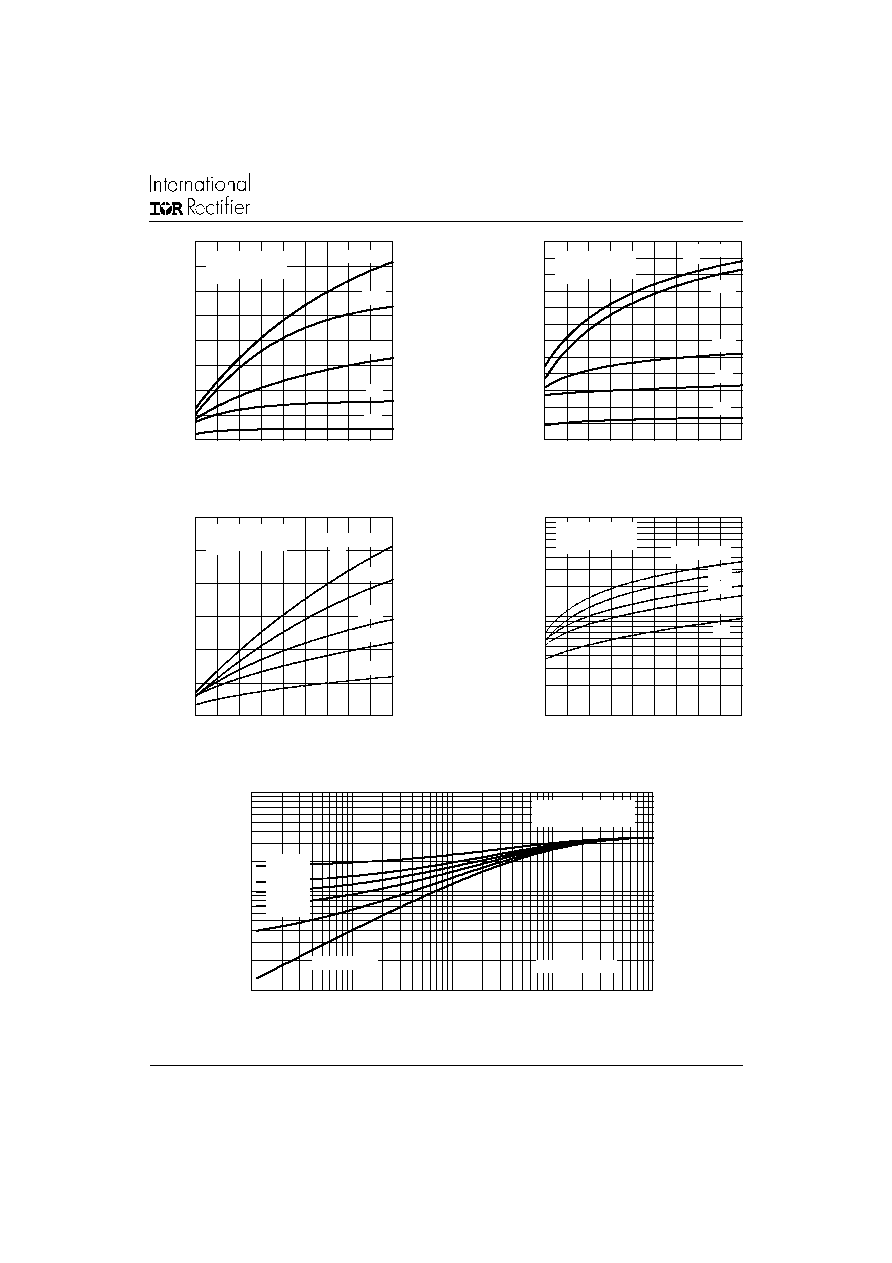
Fig. 14 - Thermal Impedance Z
thJC
Characteristics
Fig. 10 - Recovery Charge Characteristics, T
J
= 25∞C
Square Wave Pulse Duration (s)
Transient Thermal Impedance Z
thJC
(∞C/W)
0.01
0.1
1
0.0001
0.001
0.01
0.1
1
Steady State Value
(DC Operation)
Single Pulse
D = 0.50
D = 0.33
D = 0.25
D = 0.17
D = 0.08
70EPF.. Series
Rate Of Fall Of Forward Current - dI/dt (A/µs)
Maximum Reverse recovery Charge - Qrr (µC)
Rate Of Fall Of Forward Current - dI/dt (A/µs)
Maximum Reverse recovery Charge - Qrr (µC)
Fig. 11 - Recovery Charge Characteristics, T
J
= 150∞C
Maximum Reverse recovery Charge - Irr (A)
Rate Of Fall Of Forward Current - dI/dt (A/µs)
Maximum Reverse recovery Charge - Irr (A)
Rate Of Fall Of Forward Current - dI/dt (A/µs)
Fig. 12 - Recovery Current Characteristics, T
J
= 25∞C
Fig. 13 - Recovery Current Characteristics, T
J
= 150∞C
0
1
2
3
4
5
6
7
8
10 20 30 40 50 60 70 80 90 100
1 A
5 A
10 A
30 A
70EPF.. Series
T = 25 ∞C
J
I = 70 A
FM
0
1
2
3
4
5
6
7
8
9
10
11
12
10 20 30 40 50 60 70 80 90 100
1 A
5 A
10 A
30 A
I = 70 A
FM
70EPF.. Series
T = 150 ∞C
J
0
5
10
15
20
25
30
10 20 30 40 50 60 70 80 90 100
1 A
5 A
10 A
70EPF.. Series
T = 25 ∞C
J
30 A
I = 70 A
FM
1
10
100
10 20 30 40 50 60 70 80 90 100
I = 70 A
FM
30 A
10 A
5 A
1 A
70EPF.. Series
T = 150∞C
J

6
70EPF..HV QUIET
IR
Series
Bulletin I2155 rev. C 12/02
www.irf.com
Outline Table
Case Style PowIRtab
TM
Dimensions in millimeters and (inches)
Case Style PowIRtab
TM
"J" version
Dimensions in millimeters and (inches)

7
70EPF..HV QUIET
IR
Series
Bulletin I2155 rev. C 12/02
www.irf.com
Ordering Information Table
70
E
P
F
12
J
Device Code
1
5
2
4
3
1
-
Current Rating
2
-
Circuit Configuration:
E
= Single Diode
3
-
Package:
P
= TO-247AC
4
-
Type of Silicon:
F
= Fast Recovery
5
-
Voltage code: Code x 100 = V
RRM
(*)
6
-
none = PowIRtab
TM
standard
65
J
= Short Lead Version
6
10 = 1000V
12 = 1200V
6
(*)
for higher voltage up to 1600V contact factory
Base Cathode
1
Anode
2
IR WORLD HEADQUARTERS: 233 Kansas St., El Segundo, California 90245, USA Tel: (310) 252-7105
TAC Fax: (310) 252-7309
Visit us at www.irf.com for sales contact information. 12/02
Data and specifications subject to change without notice.
This product has been designed and qualified for Industrial Level.
Qualification Standards can be found on IR's Web site.