 | –≠–ª–µ–∫—Ç—Ä–æ–Ω–Ω—ã–π –∫–æ–º–ø–æ–Ω–µ–Ω—Ç: 85EPS08J | –°–∫–∞—á–∞—Ç—å:  PDF PDF  ZIP ZIP |

I
F(AV)
Sine waveform
@ T
C
= 95∞ C
I
F(RMS)
160
A
V
RRM
range
(*)
800 and 1200
V
I
FSM
1400
A
V
F
@
85A, T
J
= 25∞C
1.15
V
T
J
range
- 40 to 150
∞C
Characteristics
85EPS..
Units
85
A
Major Ratings and Characteristics
Description/ Features
The 85EPS.. rectifier
SAFE
IR
series has been
optimized for very low forward voltage drop, with
moderate leakage.
The glass passivation technology used has reliable
operation up to 150∞ C junction temperature.
Available in the new Pow
IR
tab
TM
package, this new
series is suitable for a large range of applications
combining excellent die to footprint ratio and sturdeness
connectivity for use in high current environments.
Bulletin I2139 rev. C 10/02
I
F(RMS)
= 160A
V
F
< 1.15V @ 85A
I
FSM
= 1400A
V
RRM
800 and 1200V
SAFE
IR
Series
85EPS..
INPUT RECTIFIER DIODE
1
(*)
for higher voltage up to 1600V contact factory
Case Styles
85EPS..
85EPS..J
www.irf.com

2
85EPS.. SAFE
IR
Series
Bulletin I2139 rev. C 10/02
www.irf.com
I
F(AV)
Max. Average Forward Current
85
A
@ T
C
= 95∞ C, 180∞ conduction half sine wave
I
F(RMS)
Max. RMS Forward Current
160
A
I
FSM
Max. Peak One Cycle Non-Repetitive
1400
10ms Sine pulse, rated V
RRM
applied
Surge Current
1500
10ms Sine pulse, no voltage reapplied
I
2
t
Max. I
2
t for fusing
10500
10ms Sine pulse, rated V
RRM
applied
9550
10ms Sine pulse, no voltage reapplied
I
2
t
Max. I
2
t for fusing
105000
A
2
s
t = 0.1 to 10ms, no voltage reapplied
T
J
Max. Junction Temperature Range
- 40 to 150
∞C
T
stg
Max. Storage Temperature Range
- 40 to 150
∞C
R
thJC
Max. Thermal Resistance Junction
0.35
∞C/W
DC operation
to Case
R
thJA
Max. Thermal Resistance Junction
40
∞C/W
to Ambient
R
thCS
Typical Thermal Resistance, Case to
0.2
∞C/W
Mounting surface , smooth and greased
Heatsink
wt
Approximate Weight
6 (0.21)
g (oz.)
T
Mounting Torque
Min.
6 (5)
Max.
12 (10)
Case Style
PowIRtab
TM
Thermal-Mechanical Specifications
Parameters
85EPS..
Units
Conditions
Kg-cm
(Ibf-in)
Voltage Ratings
Part Number
V
RRM
, maximum
V
RSM
, maximum non repetitive
I
RRM
peak reverse voltage
peak reverse voltage
150∞C
V
V
mA
85EPS08
800
900
85EPS12
1200
1300
V
FM
Max. Forward Voltage Drop
1.15
V
@ 85A, T
J
= 25∞C
r
t
Forward slope resistance
3.17
m
V
F(TO)
Threshold voltage
0.86
V
I
RM
Max. Reverse Leakage Current
0.1
T
J
= 25 ∞C
3.0
T
J
= 150 ∞C
Electrical Specifications
Parameters
85EPS..
Units
Conditions
T
J
= 150∞C
V
R
= rated V
RRM
mA
Absolute Maximum Ratings
Parameters
85EPS..
Units
Conditions
A
A
2
s
3

3
85EPS.. SAFE
IR
Series
Bulletin I2139 rev. C 10/02
www.irf.com
Fig. 1 - Current Rating Characteristics
Fig. 2 - Current Rating Characteristics
Fig. 4 - Forward Power Loss Characteristics
Fig. 3 - Forward Power Loss Characteristics
Fig. 5 - Forward Voltage Drop Characteristics
0
20
40
60
80
100
120
140
0
20
40
60
80
100
RMS Limit
180∞
120∞
90∞
60∞
30∞
Conduction Angle
Average Forward Current (A)
Ma
x
i
mu
m
A
v
er
a
g
e
F
o
r
w
a
r
d
P
o
w
e
r
L
o
s
s
(
W
)
85EPS.. Series
T = 150∞C
J
0
20
40
60
80
100
120
140
160
180
0
20
40
60
80
100 120 140
DC
180∞
120∞
90∞
60∞
30∞
RMS Limit
Conduction Period
Average Forward Current (A)
M
a
x
i
m
u
m
Ave
r
ag
e F
o
r
w
ar
d P
o
w
e
r
L
o
s
s
(
W
)
85EPS.. Series
T = 150∞C
J
1
10
100
1000
0
0.5
1
1.5
2
2.5
3
3.5
4
T = 25∞C
J
I
n
s
t
a
n
t
a
neo
u
s
Fo
r
w
ar
d
C
u
r
r
en
t
(
A
)
Instantaneous Forward Voltage (V)
T = 150∞C
J
85EPS.. Series
70
80
90
100
110
120
130
140
150
0
20
40
60
80
100
30∞
60∞ 90∞
120∞
180∞
Ma
x
i
mu
m
A
l
l
o
wa
b
l
e C
a
s
e
T
e
mp
e
r
a
t
u
r
e (
∞
C
)
Conduction Angle
Average Forward Current (A)
85EPS.. Series
R (DC) = 0.35 ∞C/W
thJC
70
80
90
100
110
120
130
140
150
0
20
40
60
80
100 120 140
DC
30∞
60∞
90∞
120∞
180∞
Ma
x
i
mu
m
Al
l
o
w
a
b
l
e Ca
s
e
T
e
m
p
e
r
at
u
r
e
(
∞
C)
Conduction Period
Average Forward Current (A)
85EPS.. Series
R (DC) = 0.35 ∞C/W
thJC

4
85EPS.. SAFE
IR
Series
Bulletin I2139 rev. C 10/02
www.irf.com
Fig. 8 - Thermal Impedance Z
thJC
Characteristics
Fig. 6 - Maximum Non-Repetitive Surge Current
Fig. 7 - Maximum Non-Repetitive Surge Current
900
1000
1100
1200
1300
1400
1500
1600
1
10
100
Number Of Equal Amplitude Half Cycle Current Pulses (N)
Peak Ha
lf
S
i
ne
W
a
v
e
Fo
r
w
a
r
d
Cu
r
r
en
t (
A
)
Initial T = 150∞C
@ 60 Hz 0.0083 s
@ 50 Hz 0.0100 s
J
At Any Rated Load Condition And With
Rated V Applied Following Surge.
RRM
85EPS.. Series
800
900
1000
1100
1200
1300
1400
1500
1600
1700
0.01
0.1
1
Pulse Train Duration (s)
P
e
ak
Ha
l
f
S
i
n
e
W
a
ve
F
o
r
w
a
r
d
C
u
r
r
e
n
t
(
A
)
Versus Pulse Train Duration.
Initial T = 150∞C
No Voltage Reapplied
Rated V Reapplied
RRM
J
Maximum Non Repetitive Surge Current
85EPS.. Series
0.01
0.1
1
0.0001
0.001
0.01
0.1
1
10
Square Wave Pulse Duration (s)
Steady State Value
(DC Operation)
Single Pulse
D = 0.50
D = 0.33
D = 0.25
D = 0.17
D = 0.08
th
J
C
85EPS.. Series
T
r
an
s
i
e
n
t
T
h
er
ma
l
Im
p
e
d
a
n
c
e
Z
(
∞
C/
W
)
5
85EPS.. SAFE
IR
Series
Bulletin I2139 rev. C 10/02
www.irf.com
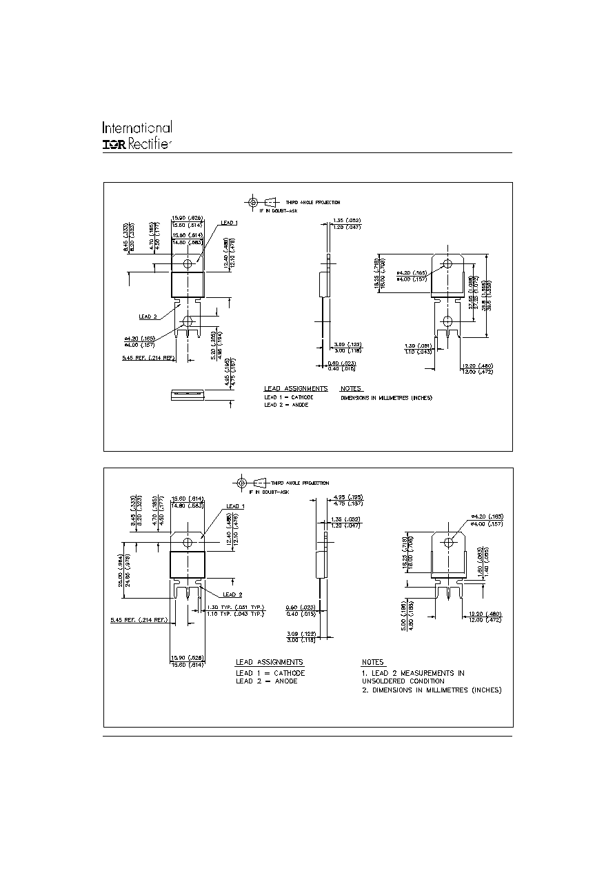
Outline Table
Case Style PowIRtab
TM
Dimensions in millimeters and (inches)
Case Style PowIRtab
TM
"J" version
Dimensions in millimeters and (inches)

6
85EPS.. SAFE
IR
Series
Bulletin I2139 rev. C 10/02
www.irf.com
Ordering Information Table
85
E
P
S
12
J
Device Code
1
5
2
4
3
1
-
Current Rating
2
-
Circuit Configuration:
E = Single Diode
3
-
Package:
P = Pow
IR
tab
TM
4
-
Type of Silicon:
S = Standard Recovery Rectifier
5
-
Voltage code: Code x 100 = V
RRM
(*)
6
-
none=PowIRtab
TM
standard
6
J
= Short Lead Version
08 = 800V
12 = 1200V
2
1
3
Anode
Anode
(*)
for higher voltage up to 1600V contact factory
6
Base Cathode
IR WORLD HEADQUARTERS: 233 Kansas St., El Segundo, California 90245, USA Tel: (310) 252-7105
TAC Fax: (310) 252-7309
Visit us at www.irf.com for sales contact information. 10/02
Data and specifications subject to change without notice.
This product has been designed and qualified for Industrial Level.
Qualification Standards can be found on IR's Web site.