 | –≠–ª–µ–∫—Ç—Ä–æ–Ω–Ω—ã–π –∫–æ–º–ø–æ–Ω–µ–Ω—Ç: 8AF4RLH | –°–∫–∞—á–∞—Ç—å:  PDF PDF  ZIP ZIP |

50 A
PRESSFIT RECTIFIER DIODES
Bulletin I20262 Rev.A 06/03
8AF SERIES
Major Ratings and Characteristics
Parameters
8AF
Units
I
F(AV)
50
A
@ T
C
150
∞C
I
F(RMS)
79
A
I
FSM
@ 50Hz
714
A
@ 60Hz
747
A
I
2
t
@ 50Hz
2546
A
2
s
@ 60Hz
2324
A
2
s
I
2
t
25455
A
2
s
V
RRM
range
100 to 800
V
T
J
- 65 to 195
o
C
IR Case Style B-47
Features and Descriptions
Convenient pressfit package
Available with and without leads
High surge capabilities
1
www.irf.com
Application
Welders, Battery charges, Alternators
8AF Series
2
Bulletin I20262 Rev.A 06/03
www.irf.com
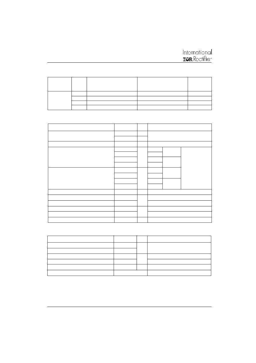
ELECTRICAL SPECIFICATIONS
Voltage Ratings
Voltage
V
RRM
, maximum repetitive
V
RSM
, maximum non-
I
RRM
max.
Type number
Code
peak reverse voltage
repetitive peak rev. voltage
@ T
J
= 150∞C
V
V
mA
1
100
150
5
2
200
300
5
4
400
500
5
8
800
900
5
8AF
I
F(AV)
Maximum average forward current
50
A
180∞ conduction, half sine wave
@ Case temperature
150
∞C
I
F(RMS)
Maximum RMS forward current
79
A
I
FSM
Maximum peak, one-cycle forward,
714
A
t = 10ms
No voltage
non-repetitive surge current
747
t = 8.3ms reapplied
600
t = 10ms
100% V
RRM
628
t = 8.3ms reapplied
Sinusoidal half wave,
I
2
t
Maximum I
2
t for fusing
2546
A
2
s
t = 10ms
No voltage Initial T
J
= T
J
max.
2324
t = 8.3ms reapplied
1800
t = 10ms
100% V
RRM
1643
t = 8.3ms reapplied
I
2
t
Maximum I
2
t for fusing
25455
A
2
s t = 0.1 to 10ms, no voltage reapplied
V
F(TO)1
Low level value of threshold voltage
0.60
V
(16.7% x
x I
F(AV)
< I <
x I
F(AV)
), T
J
= T
J
max.
V
F(TO)2
High level value of threshold voltage
0.68
(
x I
F(AV)
< I < 20 x
x I
F(AV)
), T
J
= T
J
max.
r
f1
Low level value of forward slope resistance
6.66
m
(16.7% x
x I
F(AV)
< I <
x I
F(AV)
), T
J
= T
J
max.
r
f2
High level value of forward slope resistance
6.25
(
x I
F(AV)
< I < 20 x
x I
F(AV)
), T
J
= T
J
max.
V
FM
Maximum forward voltage drop
1.45
V
T
J
= 25∞C, I
FM
=
x rated I
F(AV)
Parameter
8AF
Units Conditions
Forward Conduction
T
J
Max. junction operating temperature range
- 65 to 195
∞C
T
stg
Storage temperature range
- 65 to 195
R
thJC
Max. thermal resistance, junction to case
0.60
K/W
DC operation
R
thCS
Typical thermal resistance, case to heatsink
0.50
As per mounting details
wt
Approximate weight
10 (0.36)
g (oz)
Case style
B-47
See outline table
Parameter
8AF
Units Conditions
Thermal and Mechanical Specifications
MOUNTING: A 12.6 ± 0.02mm (0.496 to 0.497 inch) diameter hole should be drilled in heatsink, the leading edge chamfered to 0.038mm (0.015
inch) x 45∞. The diode should then be press fitted, ensuring that the sides of the diode are kept parallel to the sides of the hole.
8AF Series
3
Bulletin I20262 Rev.A 06/03
www.irf.com
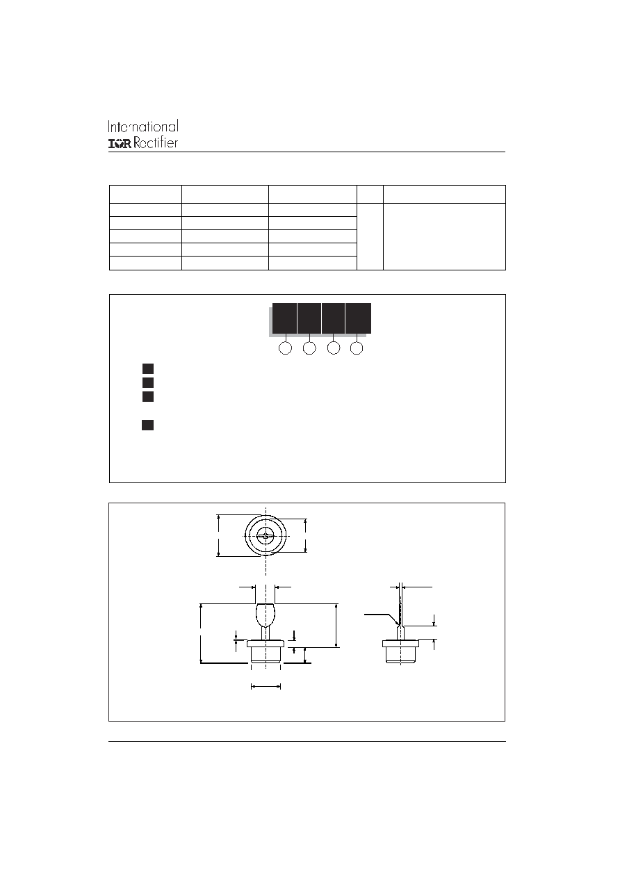
8AF
8
N
LV
1
2
3
1
- Essential part number
2
- Voltage code: Code x 100 = V
RRM
(See Voltage Ratings Table)
3
- N = Normal Polarity (cathode to case)
R = Reverse Polarity (anode to case)
4
- PP = Without Lead
LH = Horizontal Lead
LV = Vertical Lead
Available as special product - Contact Factory
4
Device Code
Ordering Information Table
R
thJC
Conduction
(The following table shows the increment of thermal resistance R
thJC
when devices operate at different conduction angles than DC)
Conduction angle
Sinusoidal conduction Rectangular conduction Units
Conditions
180∞
0.042
0.026
T
J
= T
J
max.
120∞
0.045
0.043
90∞
0.06
0.06
K/W
60∞
0.10
0.10
30∞
0.15
0.15
Outline Table
All dimensions in millimeters (inches)
6 (0.24)
22.5 (0.89)
2.4 (0.09)
16.5 (0.65)
0.5 (0.02)
12.5 (0.49)
5 (0.20)
0.9 (0.03)
15.8 (0.62)
R 0.4 (0.02)
7 (0.28)
DIA. 12.77 / 13.27
(0.50) / (0.52)

8AF Series
4
Bulletin I20262 Rev.A 06/03
www.irf.com
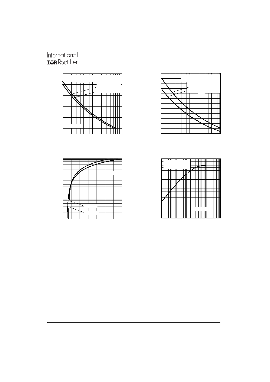
Fig. 1 - Current Ratings Characteristics
Fig. 2 - Current Ratings Characteristics
Fig. 4 - Forward Power Loss Characteristics
Fig. 3 - Forward Power Loss Characteristics
140
150
160
170
180
190
200
0
5 10 15 20 25 30 35 40 45 50 55
30∞
60∞
90∞
120∞
180∞
Ma
x
i
m
u
m
A
l
l
o
w
a
b
l
e
C
a
s
e
T
e
mp
e
r
a
t
u
r
e
(
∞
C
)
Conduction Angle
8AF Series
R (DC) = 0.6 K/W
thJC
Average Forward Current (A)
140
150
160
170
180
190
200
0
10
20
30
40
50
60
70
80
DC
30∞
60∞
90∞
120∞
180∞
M
a
x
i
m
u
m
A
l
l
o
w
a
b
l
e C
a
s
e
T
e
m
p
er
a
t
ur
e
(
∞
C
)
Conduction Period
Average Forward Current (A)
8AF Series
R (DC) = 0.6 K/W
thJC
0
25
50
75
100
125
150
R
=
1 K
/W
- D
elta
R
th
S
A
1.5
K/W
2 K
/W
3 K
/W
5 K/W
10 K/W
15 K/W
Maximum Allowable Ambient Temperature (∞C)
0
10
20
30
40
50
60
70
80
0
10
20
30
40
50
60
Average Forward Current (A)
RMS Limit
Ma
x
i
mu
m A
v
e
r
a
g
e
F
o
r
w
a
r
d
P
o
w
e
r
L
o
s
s
(
W
)
Conduction Angle
180∞
120∞
90∞
60∞
30∞
8AF Series
T = 195∞C
J
0
25
50
75
100
125
150
15 K/W
10 K/W
5 K/W
3 K/W
1.5
K/W
R
= 1
K
/W
- D
elta
R
th
S
A
2 K
/W
Maximum Allowable Ambient Temperature (∞C)
0
10
20
30
40
50
60
70
80
90
0
10
20
30
40
50
60
70
80
DC
180∞
120∞
90∞
60∞
30∞
Average Forward Current (A)
RMS Limit
M
a
x
i
m
u
m
Av
e
r
age
F
o
r
w
a
r
d P
o
w
e
r
L
o
s
s
(
W
)
Conduction Period
8AF Series
T = 195∞C
J
8AF Series
5
Bulletin I20262 Rev.A 06/03
www.irf.com
Fig. 5 - Maximum Non-Repetitive Surge Current
Fig. 6 - Maximum Non-Repetitive Surge Current
Fig. 7 - Forward Voltage Drop Characteristics
Fig. 8 - Thermal Impedance Z
thJC
Characteristic
0.01
0.1
1
0.001
0.01
0.1
1
10
th
J
C
T
r
a
n
s
i
e
n
t
T
h
er
m
a
l
Im
p
e
d
a
n
c
e
Z
(
K
/W
)
8AF Series
Square Wave Pulse Duration (s)
Steady State Value
(DC Operation)
150
200
250
300
350
400
450
500
550
600
650
700
1
10
100
P
e
a
k
H
a
l
f
S
i
n
e
W
a
v
e
F
o
r
w
a
r
d C
u
r
r
e
n
t (
A
)
Initial T = 195∞C
@ 60 Hz 0.0083 s
@ 50 Hz 0.0100 s
At Any Rated Load Condition And With
Rated V Applied Following Surge.
RRM
J
Number Of Equal Amplitude Half Cycle Current Pulses (N)
8AF Series
150
200
250
300
350
400
450
500
550
600
650
700
750
0.01
0.1
1
P
e
ak
H
a
l
f
S
i
n
e
W
a
v
e
F
o
r
w
a
r
d C
u
r
r
en
t (
A
)
Pulse Train Duration (s)
8AF Series
Maximum Non Repetitive Surge Current
Initial T = 195 ∞C
No Voltage Reapplied
Rated V Reapplied
RRM
Versus Pulse Train Duration.
J
1
10
100
1000
0
1
2
3
4
5
6
7
I
n
s
t
an
t
a
n
e
ou
s
F
o
r
w
ar
d
C
u
r
r
e
n
t
(
A
)
8AF Series
T = 195∞C
J
T = 25∞C
J
Instantaneous Forward Voltage (V)