Äîêóìåíòàöèÿ è îïèñàíèÿ www.docs.chipfind.ru
12/13/02
www.irf.com
1
ADVANCED ANALOG
EMI FILTER
HYBRID / HIGH RELIABILITY
AME50461 SERIES
Description
n
Up to 7.0 Ampere Output Current
n
Attenuation > 35dB @ 200 KHz
n
Low Profile (0.38") Seam Welded Package
n
Ceramic Feedthru Copper-Core Pins
n
Operation Over Full Military Temp. Range
n
Standard Military Drawings Available
Features
AME
Typical Connection Diagram
The AME Series of EMI filters have been designed to
provide full compliance with the input line reflected
ripple current requirement specified by CE03 of MIL-
STD-461C over the full military temperature range while
operating in conjunction with the corresponding AFL
series of DC/DC converters. These filters are offered as
part of a complete family of conversion products pro-
viding single and dual output voltages while operating
from nominal +28, +50 or +270 input line voltage. Other
converters operating with a similar switching frequency
will also benefit by use of this device.
These EMI filters are hermetically packaged in two en-
closure variations, utilizing copper-core pins to mini-
mize resistive DC losses. Three lead styles are avail-
able, each fabricated with Advanced Analog's rugged
ceramic lead-to-package seal assuring long term her-
metic seal integrity in harsh environments.
Manufactured in a facility fully qualified to MIL-PRF-
38534, these converters are available in four screen-
ing grades to satisfy a wide range of applications. The
CH grade is fully compliant to the requirements of MIL-
PRF-38534 for class H. The HB grade is fully processed
and screened to the class H requirement, but does not
include element evaluation to the class H requirement.
Both grades are tested to meet the complete
group "A" test specification over the full military
temperature range with no derating. Two grades
with more limited screening are also available
for use in less demanding applications. Varia-
tions in electrical, mechanical and screen re-
quirements can be accommodated. Contact Ad-
vanced Analog for special requirements.
AME50461
EMI Filter
AFL50XX
or Other
DC/DC Converter
+Vin
+Vin
Input Return
Input Return
+Vout
+Vout
Output Return
Output Return
To Additional Converters up to Total
of Filter Rated Output Current
R
L
R
L
System
Bus
AFL50XX
or Other
DC/DC Converter
+Vout
Output Return
+Vin
Input Return
Note: Filter and Converter
Cases Should be
Electrically Connected
PD - 94595
2
www.irf.com
AME50461 Series
Specifications
Electrical Characteristics
-55°C
TCASE
+125°C, -40
VIN
+40 unless otherwise specified
Notes to Specifications
1.
Operation above maximum ratings may cause permanent damage to the device. Operation at maximum ratings may degrade
performance and affect reliability.
2.
Device can tolerate ± 300 Volt transient whose duration is
100 ms when R
S
0.5
.
3.
Derate Output Current linearly from 100% at 125°C to 0 at 135°C.
4.
DC resistance is the total resistance of the device and includes the sum of the
input to output resistance and the return in to return
out resistance paths.
ABSOLUTE MAXIMUM RATINGS
Note 1
Input Voltage
-300V to +300V
Note 2
Input Current
7.0 A
Lead Soldering Temperature
300°C for 10 seconds
Case Temperature
Operating
-55°C to +125°C
Storage
-65°C
to
+135°C
Parameter
Group A
Subgroups
Test Conditions
Min
Nom
Max
Unit
INPUT VOLTAGE
Steady State
Transient
Note 2
-100
-300
+100
+300
V
DC
OUTPUT VOLTAGE
1, 2, 3
V
OUT
= V
IN
- I
IN
(R
DC
)
V
DC
OUTPUT CURRENT
Note 3
7.0
A
DC
DC RESISTANCE
Note 4
1
T
C
= 25°C
T
C
= 125°C
60
100
m
POWER DISSIPATION
Maximum Current
T
C
= 25°C
T
C
= 125°C
2.94
4.90
w
NOISE REDUCTION
200 KHz - 500 KHz
500 KHz - 1 MHz
1 MHz - 50 MHz
35
60
65
dB
ISOLATION
1
Any Pin to Case
Tested @ 500VDC
100 M
CAPACITANCE
Measured Between Any Pin and Case
40
nF
DEVICE WEIGHT
Slight Variations with Case Style
95
gms
www.irf.com
3
AME50461 Series
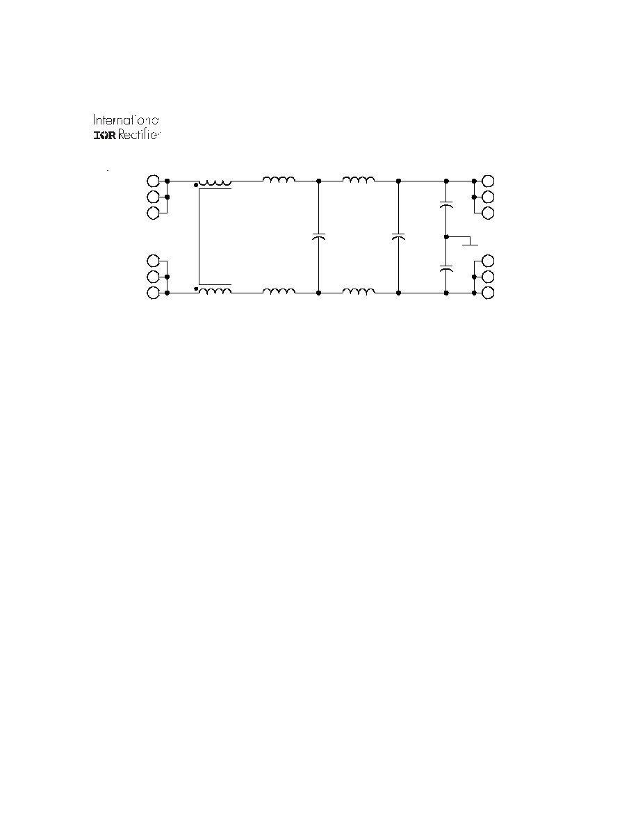
AME50461 Block Diagram
Refer to last page for Pin Designation
Circuit Operation and Application Information
The AME series of filters employ three stages of fil-
tering in a low pass configuration designed to at-
tenuate the higher frequency components of ripple
currents generated by high frequency switching DC/
DC converters. The Block Diagram describes the
general arrangement of the principal elements which
have been connected to provide both differential and
normal mode buffering between the input and out-
put terminals.
1
To calculate the input current (
iin) requirement of any one converter, first determine the maximum output power by
multiplying output voltage by maximum load current, divide this power by the efficiency to obtain input power and then divide
input power by input voltage to obtain the input current (
iin). Note that to obtain worst case input current, you must use
maximum load current, minimum efficiency and minimum line voltage in this calculation.
7
1 2
1
6
2 0 n F
2 0 n F
C a s e
O u t p u t
O u t p u t
R e t u r n
Input
Input
R e t u r n
2
3
5
4
1 1
1 0
8
9
Employing only passive elements, AME filter opera-
tion is initiated simply by insertion into the input power
path between one or more DC/DC converters and
their input DC voltage bus. In this connection, out-
put pins of the filter will be connected to input pins of
the converters.
When a single AME filter is used in conjunction with
multiple DC/DC converters, the use will be limited
to the maximum output current capability specified
in the AME electrical table.
1
A typical connection
utilizing one filter to drive two converters is illus-
trated on page1.
Although expressly designed to complement the AFL
series of DC/DC converters, the AME50461 filters
can be successfully operated in conjunction with
other converters in the Advanced Analog line in-
cluding the ASA, AHF, AHV and ATR series.
4
www.irf.com
AME50461 Series
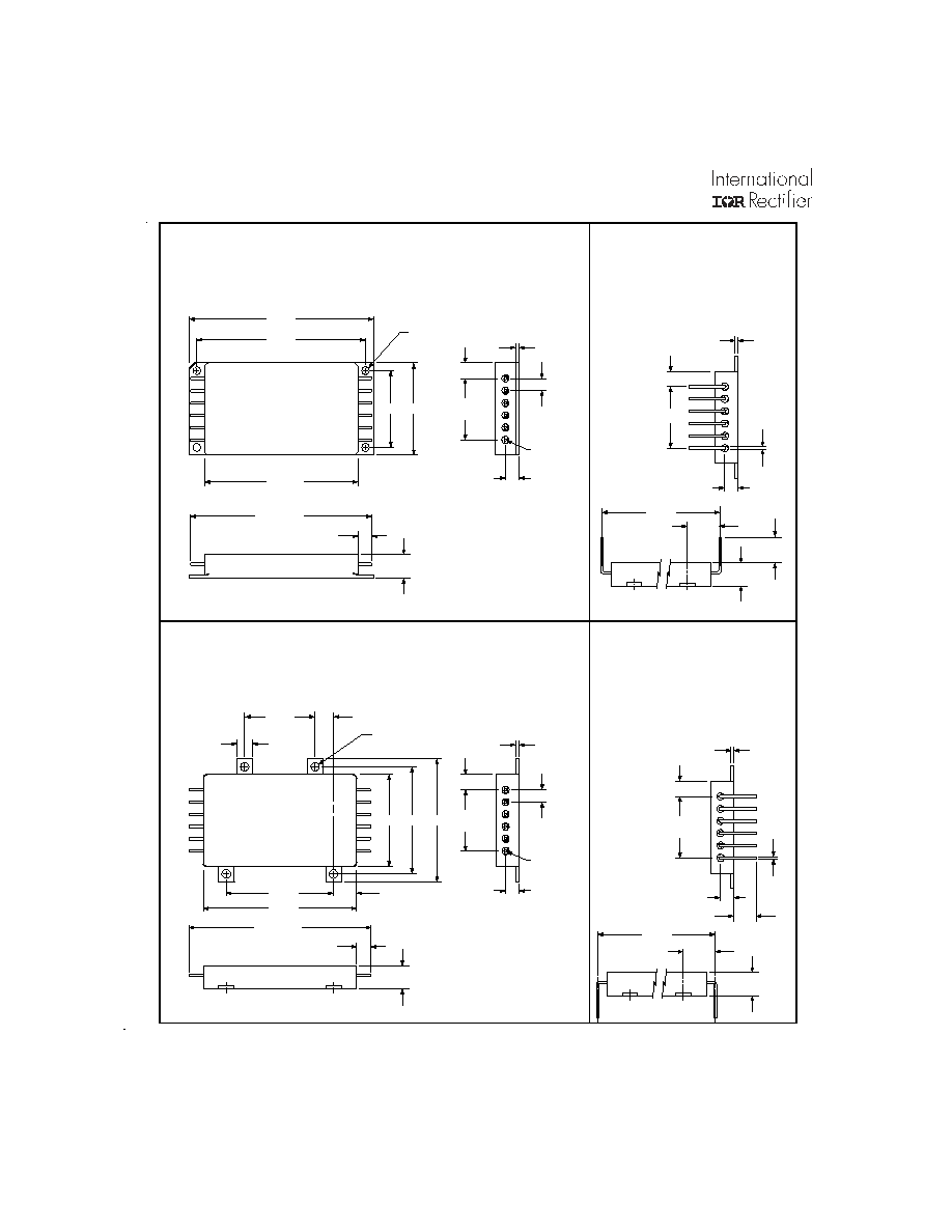
AME50461 Case Style Outlines
Case X
Case W
Pin Variation of Case Y
1 . 2 6 0 1 . 5 0 0
2 . 5 0 0
2 . 7 6 0
3 . 0 0 0
ø 0.128
0 . 2 5 0
1 . 0 0 0
R e f
0 . 2 0 0 T y p
Non-cum
0 . 0 5 0
0 . 2 2 0
Pin
ø 0 . 0 4 0
0 . 2 3 8 m a x
0 . 3 8 0
M a x
2 . 9 7 5 m a x
1
6
7
12
0 . 0 5 0
0 . 2 2 0
0 . 2 5 0
1 . 0 0 0
Pin
ø 0 . 0 4 0
0 . 5 2 5
0 . 3 8 0
M a x
2 . 8 0 0
0 . 4 2
Case Y
Case Z
Pin Variation of Case Y
1 . 5 0 0 1 . 7 5 0
2 . 5 0 0
0.25 typ
1 . 1 5 0
0 . 0 5 0
0 . 2 2 0
1
6
7
12
1 . 7 5 0
0 . 3 7 5
2 . 0 0
0 . 2 5 0
1 . 0 0 0
R e f
0 . 2 0 0 T y p
Non-cum
Pin
ø 0 . 0 4 0
0 . 3 0 0
ø 0 . 1 4 0
0 . 2 3 8 m a x
0 . 3 8 0
M a x
2 . 9 7 5 m a x
0 . 0 5 0
0 . 2 2 0
0 . 2 5 0
1 . 0 0 0
R e f
Pin
ø 0 . 0 4 0
0 . 5 2 5
0 . 3 8 0
M a x
2 . 8 0 0
0 . 3 6
Tolerances, unless otherwise specified:
.XX
=
±0.010
.XXX = ±0.005
www.irf.com
5
AME50461 Series
Pin Designation
WORLD HEADQUARTERS: 233 Kansas St., El Segundo, California 90245, Tel: (310) 322 3331
ADVANCED ANALOG: 2270 Martin Av., Santa Clara, California 95050, Tel: (408) 727-0500
Visit us at www.irf.com for sales contact information.
Data and specifications subject to change without notice. 12/02
Pin No.
Designation
1 Positive
Input
2 Positive
Input
3 Positive
Input
4 Input
Return
5 Input
Return
6 Input
Return
7 Output
Return
8 Output
Return
9 Output
Return
10 Positive
Output
11 Positive
Output
12 Positive
Output
Part Numbering
AME 50 461 X / CH
Model
Input Voltage
2 8 = 2 8 V
5 0 = 5 0 V
2 7 0 = 2 7 0 V
Applicable
Military Test
Standard
Case Style
W , X , Y , Z
Screening
--
, E S , H B , C H
Available Screening Levels and Process Variations for AME50461 Series
Requirement
MIL-STD-883
Method
No
Suffix
ES
Suffix
HB
Suffix
CH
Suffix
Temperature Range
-20 to +85°C
-55°C to +125°C
-55°C to +125°C
-55°C to +125°C
Element Evaluation
MIL-PRF-38534
Internal Visual
2017
¬
Yes Yes Yes
Temperature Cycle
1010
Cond B
Cond C
Cond C
Constant Acceleration
2001
500g
Cond A
Cond A
Burn-in 1015
48hrs@
85
°
C
48hrs@ 125°C
160hrs @ 125°C
160hrs @ 125°C
Final Electrical
(Group A)
MIL-PRF-38534
& Specification
25°C
25°C
-55, +25, +125°C
-55, +25, +125°C
Seal, Fine & Gross
1014
Cond A
Cond A, C
Cond A, C
Cond A, C
External Visual
2009
¬
Yes Yes Yes
*
Per Commercial Standards