 | ÐлекÑÑоннÑй компоненÑ: SD600R | СкаÑаÑÑ:  PDF PDF  ZIP ZIP |
Äîêóìåíòàöèÿ è îïèñàíèÿ www.docs.chipfind.ru
Typical Applications
Converters
Power supplies
Machine tool controls
High power drives
Medium traction applications
Parameters
Units
SD600N/R
04 to 20
25 to 32
I
F(AV)
600
600
A
@ T
C
92
54
°C
I
F(RMS)
940
940
A
I
F S M
@
50Hz
13000
10500
A
@ 60Hz
13600
11000
A
I
2
t
@
50Hz
845
551
K A
2
s
@ 60Hz
772
503
K A
2
s
V
R R M
range
400 to 2000
2500
to 3200
V
T
J
-
40
to 180
- 40 to 150
°C
Major Ratings and Characteristics
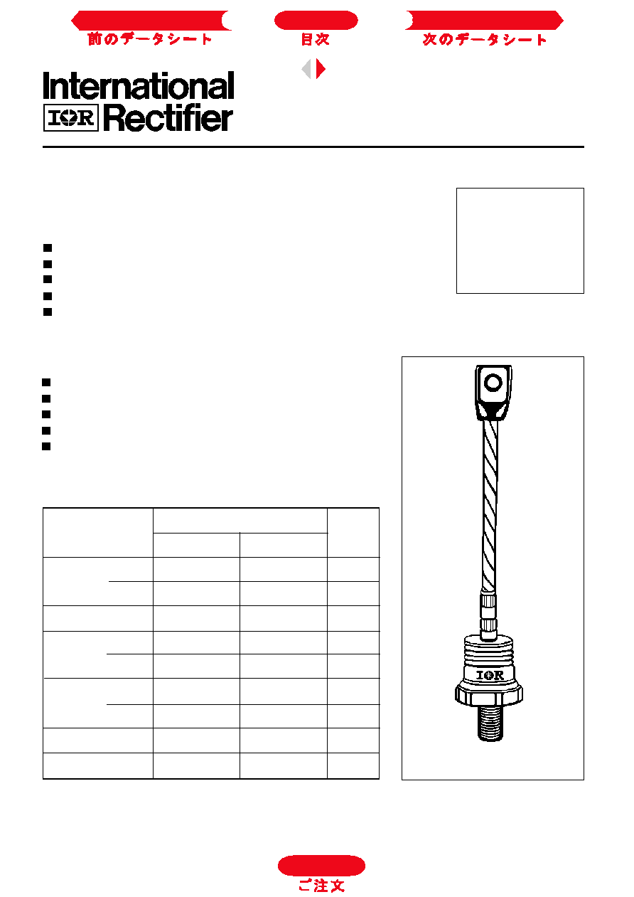
case style
B-8
SD600N/R SERIES
STANDARD RECOVERY DIODES
600A
Stud Version
Bulletin I2070/B
Features
Wide current range
High voltage ratings up to 3200V
High surge current capabilities
Stud cathode and stud anode version
Standard JEDEC types
Next Data Sheet
Index
Previous Datasheet
To Order
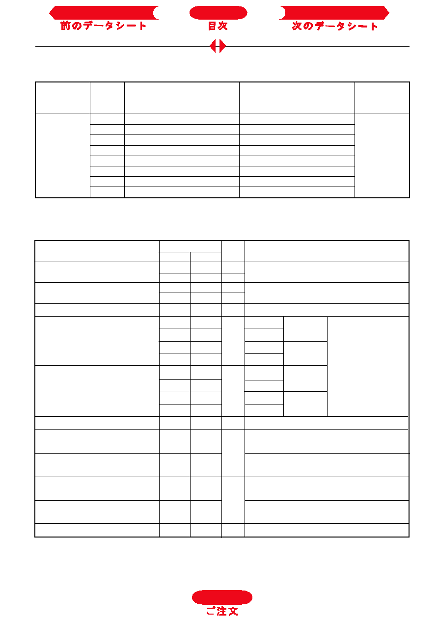
SD600N/R Series
SD600N/R
35
Voltage
V
R R M
, maximum repetitive
V
R S M
, maximum non-
I
RRM
max.
Type number
Code
peak reverse voltage
repetitive peak rev. voltage
@ T
J
= T
J
max.
V
V
m A
04
400
500
08
800
900
12
1200
1300
16
1600
1700
20
2000
2100
25
2500
2600
28
2800
2900
32
3200
3300
ELECTRICAL SPECIFICATIONS
Voltage Ratings
I
F(AV)
Max. average forward current
600
600
A
180° conduction, half sine wave
@ Case temperature
92
54
°C
I
F(AV)
Max. average forward current
570
375
A
180° conduction, half sine wave
@ Case temperature
100
100
°C
I
F(RMS)
Max. RMS forward current
940
940
A
DC @ T
C
= 75°C (04 to 20), T
C
= 36°C (25 to 32)
I
FSM
Max. peak, one-cycle forward,
13000
10500
t = 10ms
No voltage
non-repetitive surge current
13600
11000
t = 8.3ms
reapplied
10900
8830
t = 10ms
100% V
RRM
11450
9250
t = 8.3ms
reapplied
Sinusoidal half wave,
I
2
t
Maximum I
2
t for fusing
845
551
t = 10ms
No voltage
Initial T
J
= T
J
max.
772
503
t = 8.3ms
reapplied
598
390
t = 10ms
100% V
RRM
546
356
t = 8.3ms
reapplied
I
2
t
Maximum I
2
t for fusing
8450
5510
KA
2
s
t = 0.1 to 10ms, no voltage reapplied
V
F(TO)1
Low level value of threshold
voltage
V
F(TO)2
High level value of threshold
voltage
r
f
1
Low level value of forward
slope resistance
r
f
2
High level value of forward
slope resistance
V
FM
Max. forward voltage drop
1.31
1.44
V
I
pk
= 1500A, T
J
= T
J
max, t
p
= 10ms sinusoidal wave
SD600N/R
04 to 20
25 to 32
Parameter
Units
Conditions
0.31
0.38
(I >
x I
F(AV)
),T
J
= T
J
max.
0.35
0.40
(16.7% x
x I
F(AV)
< I <
x I
F(AV)
), T
J
= T
J
max.
m
0.87
0.88
(I >
x I
F(AV)
),T
J
= T
J
max.
0.78
0.84
(16.7% x
x I
F(AV)
< I <
x I
F(AV)
), T
J
= T
J
max.
V
KA
2
s
A
Forward Conduction
Next Data Sheet
Index
Previous Datasheet
To Order
SD600N/R Series
Parameter
Units
Conditions
SD600N/R
04 to 20
25 to 32
T
J
Max. junction operating temperature range
-40 to 180
-40 to 150
T
stg
Max. storage temperature range
-55 to 200
-55 to 200
R
thJC
Max. thermal resistance, junction to case
0.1
DC operation
R
thCS
Max. thermal resistance, case
Mounting surface, smooth, flat and
to heatsink
greased
T
Max. allowed mounting torque ±10%
50
Nm
Not lubricated threads
wt
Approximate weight
454
g
Case style
B - 8
See Outline Table
°C
0.04
K/W
Thermal and Mechanical Specifications
180°
0.012
0.008
T
J
= T
J
max.
120°
0.014
0.014
90°
0.017
0.019
60°
0.025
0.026
30°
0.042
0.042
Conduction angle
Sinusoidal conduction
Rectangular conduction Units
Conditions
K/W
R
thJC
Conduction
(The following table shows the increment of thermal resistence R
thJC
when devices operate at different conduction angles than DC)
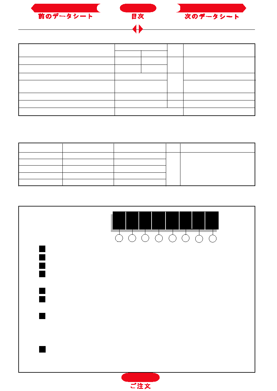
Ordering Information Table
1
2
3
4
5
6
Device Code
SD
60
0
N
32
P
S
C
8
7
1
-
Diode
2
-
Essential part number
3
-
0 = Standard recovery
4
-
N = Stud Normal Polarity (Cathode to Stud)
R = Stud Reverse Polarity (Anode to Stud)
5
-
Voltage code: Code x 100 = V
R R M
(See Voltage Ratings table)
6
-
P = Stud base B-8 3/4" 16UNF-2A
M = Stud base B-8 M24 X 1.5
7
-
S = Isolated lead with silicone sleeve
(Red = Reverse Polarity; Blue = Normal Polarity)
T = Threaded Top Terminal 3/8" 24UNF-2A
None = Non isolated lead
8
-
C = Ceramic Housing
NOTE: Available for rotating applications (Contact factory)
To Order
Next Data Sheet
Index
Previous Datasheet
SD600N/R Series
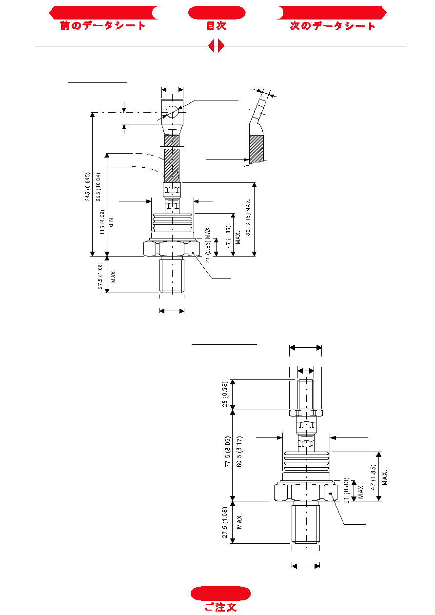
Outlines Table
Case Style B-8
All dimensions in millimeters (inches)
Case Style B-8 with top thread terminal 3/8"
All dimensions in millimeters (inches)
26 (1.023) MAX.
10.5 (0.41) DIA.
12 (0.47) MIN.
38 (1.5)
DIA. MAX.
CERAMIC HOUSING
SW 45
C.S. 70mm
5(0.20) ± 0.3(0.01)
2
3/4"-16UNF-2A *
* FOR METRIC DEVICE: M24 x 1.5 - SCREW LENGTH -- 21(0.83) MAX.
38 (1.5)
DIA. MAX.
CERAMIC HOUSING
SW 45
3/4"-16UNF-2A *
3/8"-24UNF-2A
17 (0.67) DIA.
* FOR METRIC DEVICE: M24 x 1.5 - SCREW LENGTH -- 21(0.83) M
To Order
Next Data Sheet
Index
Previous Datasheet
SD600N/R Series
20
40
60
80
100 120 140 160 180
Maximum Allowable Ambient Temperature (°C)
1 K/W
R
= 0
.02
K
/W
- D
e
lta
R
th
SA
0.0
4 K
/W
0.0
8 K
/ W
0.1
K
/W
0.2
K/ W
0.4 K/
W
0.6 K
/ W
1.8 K/W
0
1 0 0
2 0 0
3 0 0
4 0 0
5 0 0
6 0 0
7 0 0
8 0 0
0
1 0 0
2 0 0
3 0 0
4 0 0
5 0 0
6 0 0
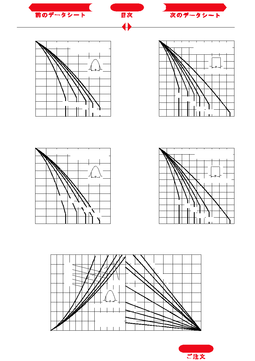
180°
120°
90°
60°
30°
RMS Limit
Conduction Angle
M
a
x
i
m
u
m
A
v
e
r
a
g
e
F
o
r
w
a
r
d
P
o
w
e
r
L
o
s
s
(
W
)
Average Forward Current (A)
SD600N/ R Series
(400V to 2000V)
T = 180°C
J
Fig. 5 - Forward Power Loss Characteristics
50
60
70
80
90
100
110
120
130
140
150
0
100
200
300
400
500
600
700
30°
60°
90°
120°
180°
Average Forward Current (A)
Conduction Angle
M
a
x
i
m
u
m
A
l
l
o
w
abl
e
C
a
s
e
T
e
m
per
at
u
r
e
(
°
C
)
SD600N/ R Series (2500V to 3200V)
R (DC) = 0.1 K/ W
thJC
30
40
50
60
70
80
90
100
110
120
130
140
150
0
200
400
600
800
1000
30°
60°
90°
180°
DC
120°
Avera ge Forward Current (A)
Conduction Period
M
a
x
i
mu
m A
l
l
o
w
a
b
l
e
C
a
s
e
T
em
pe
r
a
t
u
r
e
(
°
C
)
SD600N/R Series (2500V to 3200V)
R (DC) = 0.1 K/ W
thJC
Fig. 3 - Current Ratings Characteristics
Fig. 4 - Current Ratings Characteristics
Fig. 1 - Current Ratings Characteristics
Fig. 2 - Current Ratings Characteristics
70
80
90
100
110
120
130
140
150
160
170
180
0
200
400
600
800
1000
30°
60°
90°
180°
DC
120°
Average Forward Current (A)
Conduction Period
M
a
x
i
m
u
m
A
l
l
o
w
abl
e C
a
s
e
T
e
m
per
at
u
r
e (
°
C
)
R (DC) = 0.1 K/ W
thJC
SD600N/R Series (400V to 2000V)
80
90
100
110
120
130
140
150
160
170
180
0
100
200
300
400
500
600
700
30°
60°
90°
120°
180°
Average Forward Current (A)
Conduction Angle
M
a
x
i
m
u
m
A
l
l
o
w
abl
e C
a
s
e
T
e
m
p
e
r
at
u
r
e
(
°
C
)
R (DC) = 0.1 K/W
thJC
SD600N/ R Series (400V to 2000V)
To Order
Next Data Sheet
Index
Previous Datasheet