Dimensions are shown in mm (inch)
Dimensions subject to change
58
RF Coaxial Connectors
1.6 / 5.6
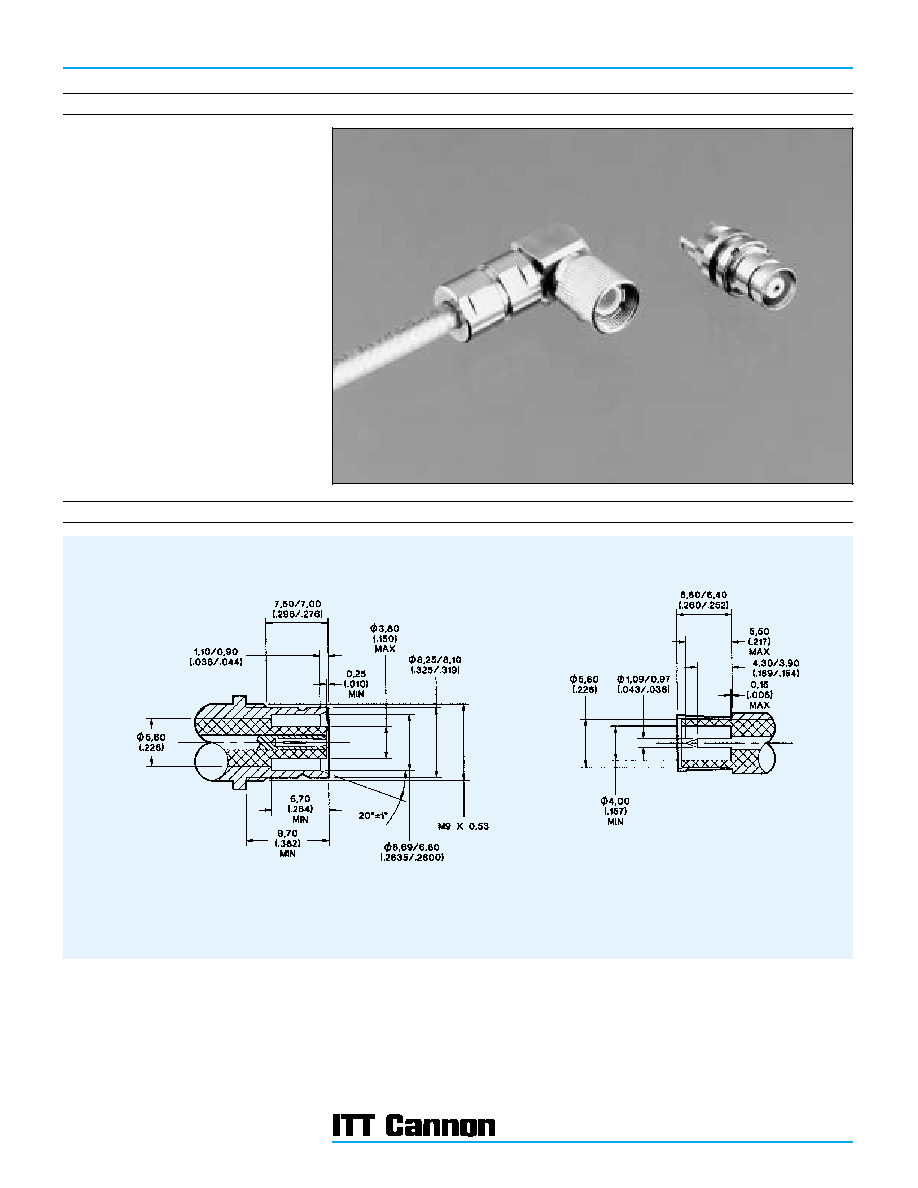
Introduction
The ITT Cannon range of 1.6/5.6 Connectors are
suitable for use in 75 ohm communication
systems. These connectors have become the
recognised standard in telecommunication
systems in many parts of the world.
Designed to meet the requirements of DIN 47295,
CECC 22240 and IEC 169-13, these connectors
feature screw couplings to ensure mating integrity
and snap coupling for ease of connection and
disconnection (New Push-Pull coupling will be
introduced in 1996).
The range of parts shown in this publication
includes plug and jack connectors for a variety of
cables, together with PCB styles and U links. Other
cable types and connector styles may be available
on request.
Mating Interfaces
JACK
PLUG

Dimensions are shown in mm (inch)
Dimensions subject to change
59
1.6/5.6
RF Coaxial Connectors
1.6 / 5.6
Specifications
ELECTRICAL
Impedance
75
nominal
Frequency Range
0 - 1 GHz
Voltage Rating *
At Sea Level = 330 Vrms
Insulation Resistance
10 G
minimum
Contact Resistance
Inner contact = 4 m
maximum
Outer contact = 2 m
maximum
Reflection Coefficient *
With f = 0.1 GHz
= 0.02 maximum
With f = 0.1 � 0.5 GHz
= 0.04 maximum
With f = 0.5 � 1.0 GHz
= 0.10 maximum
MECHANICAL
Withdrawal force inner female contact
0.5 N (0.11 lbs.) minimum
Withdrawal force inner male contact
1.7 N (0.38 lbs.) minimum
Insertion force between jacks and plugs
Screw types: 12 N (2.7 lbs.) maximum. Push-pull type: 20 N (4.5 lbs.) maximum
Withdrawal force between jacks and plugs
Screw types: 22 N (4.9 lbs.) minimum. Push-pull type: 20 N (4.5 lbs.) maximum
Materials
Bodies and nuts: Brass. Inner male contact: Brass.
Inner female contact and outer male contact: Beryllium copper. Insulators: PTFE.
Crimp ferrules: Annealed copper alloy.
Finish/Plating
Contact surfaces: Gold over nickel. Female bodies: Gold over nickel. Male bodies: Nickel or silver. Nuts
and crimp ferrules: Nickel
ENVIRONMENTAL
Temperature Rating
-40
�
C to 85
�
C
GENERAL
Connector Durability
500 matings minimum
Standards
CECC 22240, DIN 47295, IEC 169-13
* Guideline value only� will depend on cable and connector type

Dimensions are shown in mm (inch)
Dimensions subject to change
60
RF Coaxial Connectors
1.6 / 5.6
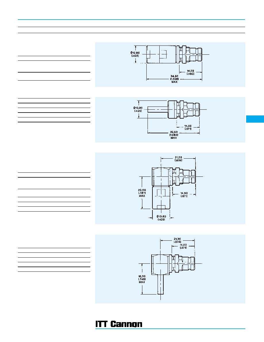
Cable Plugs
OTHER CABLE TYPES AVAILABLE ON REQUEST
Assembly Instruction BBAI-1244 (Apply ITT Cannon Sales Dept.)
Straight Clamp Plug
Screw Coupling
Part Number
Cable Numbers
F50-A07-3002A90
2YCCY 0.4/2.5,
2YC(MS)CY 0.4/2.5
ST121
F50-A07-3003A90
2YCY 0.7/4.4
RG59B/U, ST120, ST214
Straight Crimp Plug
Screw Coupling
Part Number
Cable Numbers
F50-A24-3002A90
2YCCY 0.4/2.5
F50-A24-3003A90
2YCY 0.7/4.4
F50-A24-3033A90
BT2003
F50-A24-3035A90
BT3002, TZC75024
Assembly Instructions
F50-A24-3002A90
BBAI-1245
F50-A24-3003A90
BBAI-1246
F50-A24-3033A90
BBAI-1245
F50-A24-3035A90
BBAI-1246
(Apply ITT Cannon Sales Dept.)
Assembly Instruction BBAI-1231 (Apply ITT Cannon Sales Dept.)
Right Angle Clamp Plug
Screw Coupling
Part Number
Cable Numbers
F50-A11-3002A90
2YCCY 0.4/2.5,
2YC(MS)CY 0.4/2.5
ST121
F50-A11-3003A90
2YCY 0.7/4.4
RG59B/U, ST120, ST214
Right Angle Crimp Plug
Screw Coupling
Part Number
Cable Numbers
F50-A28-3002A90
2YCCY 0.4/2.5
F50-A28-3003A90
2YCY 0.7/4.4
F50-A28-3033A90
BT2003
F50-A28-3035A90
BT3002, TZC75024
Assembly Instructions
F50-A28-3002A90
BBAI-1247
F50-A28-3003A90
BBAI-1248
F50-A28-3033A90
BBAI-1247
F50-A28-3035A90
BBAI-1248
(Apply ITT Cannon Sales Dept.)
Dimensions are shown in mm (inch)
Dimensions subject to change
61
1.6/5.6
RF Coaxial Connectors
1.6 / 5.6
Cable Jacks
OTHER CABLE TYPES AVAILABLE ON REQUEST
Straight Bulkhead Clamp Jack
All Couplings
Part Number
Cable Numbers
F50-A10-3002A90
2YCCY 0.4/2.5,
2YC(MS)CY 0.4/2.5
ST121
F50-A10-3003A90
2YCY 0.7/4.4
RG59B/U, ST120, ST214
Straight Bulkhead Crimp Jack
All Couplings
Part Number
Cable Numbers
F50-A27-3002A90
2YCCY 0.4/2.5
F50-A27-3003A90
2YCY 0.7/4.4
F50-A27-3033A90
BT2003
F50-A27-3035A90
BT3002, TZC75024
Assembly Instructions
F50-A27-3002A90
BBAI-1245
F50-A27-3003A90
BBAI-1246
F50-A27-3033A90
BBAI-1245
F50-A27-3035A90
BBAI-1246
(Apply ITT Cannon Sales Dept.)
Right Angle Bulkhead Clamp Jack
All Couplings
Part Number
Cable Numbers
F50-A12-3002A90
2YCCY 0.4/2.5,
2YC(MS)CY 0.4/2.5
ST121
F50-A12-3003A90
2YCY 0.7/4.4
RG59B/U, ST120, ST214
F50-A12-3033A90
BT2003
F50-A12-3035A90
BT3002, TZC75024
F50-A12-3045A90
2.5C-2V
Right Angle Bulkhead Crimp Jack
All Couplings
Part Number
Cable Numbers
F50-A30-3002A90
2YCCY 0.4/2.5
F50-A30-3003A90
2YCY 0.7/4.4
F50-A30-3033A90
BT2003
F50-A30-3035A90
BT3002, TZC75024
Assembly Instructions
F50-A30-3002A90
BBAI-1247
F50-A30-3003A90
BBAI-1248
F50-A30-3033A90
BBAI-1247
F50-A30-3035A90
BBAI-1248
(Apply ITT Cannon Sales Dept.)
Mounting Plan BB (Page 109). Maximum Panel Thickness 2,00 (.078). Assembly Instruction BBAI-1244*
Mounting Plan BB (Page 109). Maximum Panel Thickness 2,00 (.078)
Mounting Plan BB (Page 109). Maximum Panel Thickness 2,00 (.078). Assembly Instruction BBAI-1231*
Mounting Plan BB (Page 109). Maximum Panel Thickness 2,00 (.078)
* Apply ITT Cannon Sales Department
Dimensions are shown in mm (inch)
Dimensions subject to change
62
RF Coaxial Connectors
1.6 / 5.6
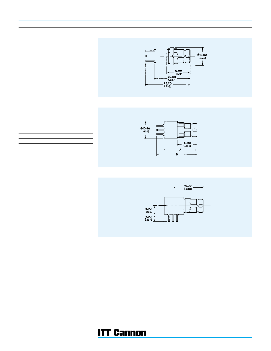
Printed Circuit Board Connectors
Mounting Plan P & E (Page 108). Maximum Panel Thickness 1,50 (.059)
Straight Panel Jack
All Couplings
Part Number
F50-A51-9001A9A
Mounting Plan B (Page 108)
Straight Jack
All Couplings
Part Number
A
B
F50-A51-9002A9A
20,80 (.818)
25,00 (.984)
F50-A51-9003A9A
21,50 (.846)
28,50 (1.122)
Mounting Plan B (Page 108)
Right Angle Jack
All Couplings
Part Number
F50-A53-9001A9A