© 2000 IXYS All rights reserved
1 - 2
V
RSM
V
(BR)min
ˇx
V
RRM
Standard
Avalanche
V
V
V
Types
Types
900
800
DS
2-08A
1300
1300
1200
DS
2-12A
DSA
2-12A
1700
1750
1600
DSA
2-16A
1900
1950
1800
DSA
2-18A
x
Only for Avalanche Diodes
Symbol
Test Conditions
Maximum Ratings
I
F(RMS)
T
VJ
= T
VJM
7
A
I
F(AV)M
T
amb
= 45
∞
C; R
thJA
=
30 K/W; 180
∞
sine
3.6
A
T
amb
= 45
∞
C; R
thJA
= 115 K/W; 180
∞
sine
1.2
A
P
RSM
DSA types, T
VJ
= 25
∞
C, t
p
= 10
m
s
2.5
kW
I
FSM
T
VJ
= 45
∞
C;
t = 10 ms (50 Hz), sine
120
A
V
R
= 0
t = 8.3 ms (60 Hz), sine
127
A
T
VJ
= T
VJM
t = 10 ms (50 Hz), sine
100
A
V
R
= 0
t = 8.3 ms (60 Hz), sine
106
A
I
2
t
T
VJ
= 45
∞
C
t = 10 ms (50 Hz), sine
72
A
2
s
V
R
= 0
t = 8.3 ms (60 Hz), sine
68
A
2
s
T
VJ
= T
VJM
t = 10 ms (50 Hz), sine
50
A
2
s
V
R
= 0
t = 8.3 ms (60 Hz), sine
47
A
2
s
T
VJM
180
∞
C
T
VJ
-40...+180
∞
C
T
stg
-40...+180
∞
C
Weight
2.4
g
V
RRM
= 800-1800 V
I
F(RMS)
= 7 A
I
F(AV)M
= 3.6 A
A = Anode C = Cathode
Features
q
International standard package
q
Axial wire connexions
q
Planar glassivated chips
Applications
q
Low power rectifiers
q
Field supply for DC motors
q
Power supplies
q
High voltage rectifiers
Advantages
q
Space and weight savings
q
Simple PCB mounting
q
Improved temperature and power
cycling
q
Reduced protection circuits
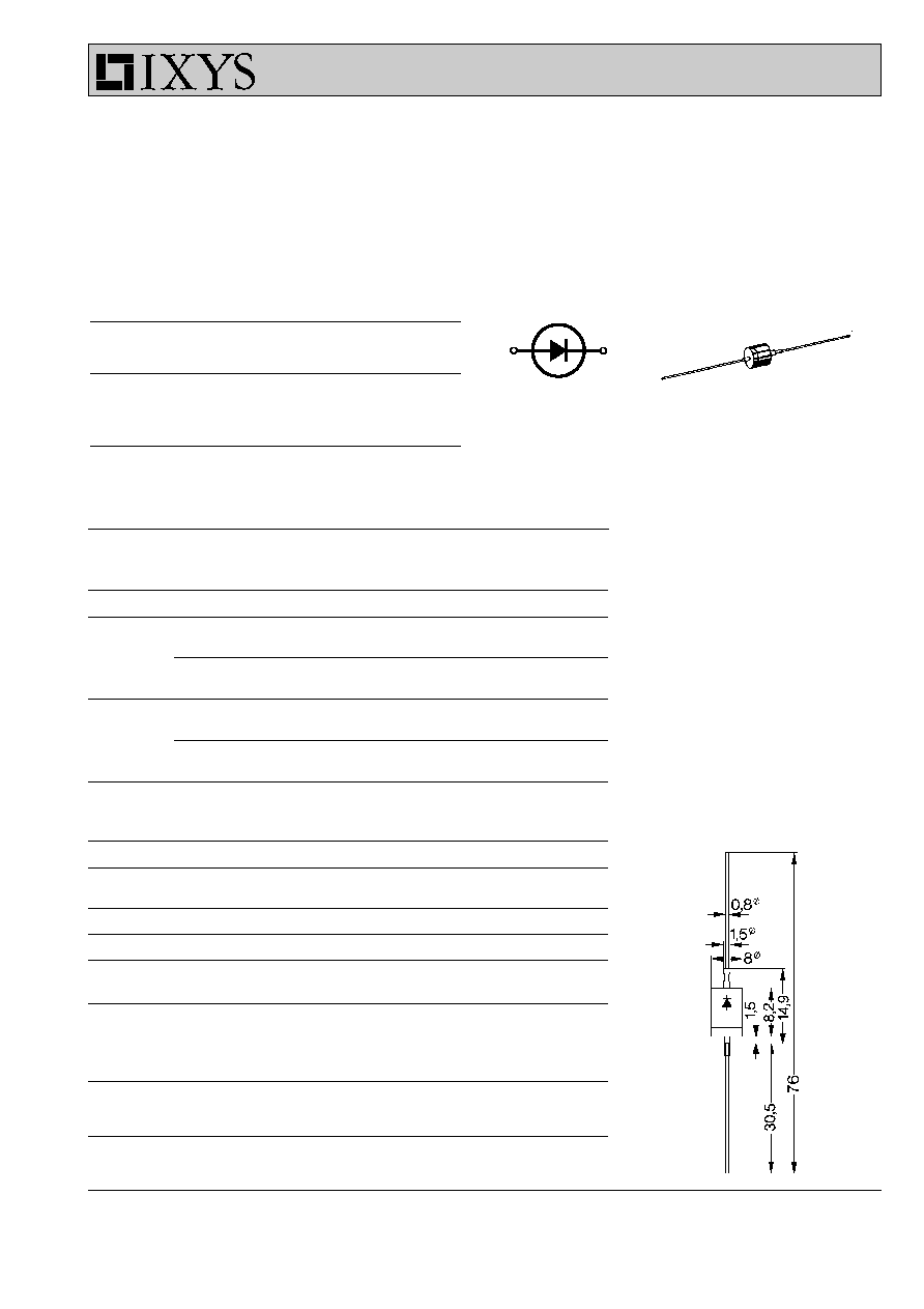
Dimensions in mm (1 mm = 0.0394")
Symbol
Test Conditions
Characteristic Values
I
R
T
VJ
= 180∞C; V
R
= V
RRM
£
2
mA
V
F
I
F
= 7 A; T
VJ
= 25
∞
C
£
1.25
V
V
T0
For power-loss calculations only
0.85
V
r
T
T
VJ
= T
VJM
43
m
W
R
thJA
Forced air cooling with 1.5 m/s, T
amb
= 45
∞
C
30
K/W
Soldered between 2 cooling fins, T
amb
= 45
∞
C
37
K/W
Soldered onto PC board (25 mm), T
amb
= 45
∞
C
75
K/W
Free air cooling, T
amb
= 45
∞
C
115
K/W
d
S
Creepage distance on surface
2.25
mm
d
A
Strike distance through air
2.25
mm
a
Max. allowable acceleration
100
m/s
2
Data according to IEC 60747
IXYS reserves the right to change limits, test conditions and dimensions
DS
2
DSA 2
Rectifier Diode
Avalanche Diode
A
C
A
C
C
A

© 2000 IXYS All rights reserved
2 - 2
10
-3
10
-2
10
-1
10
0
10
1
0
20
40
60
80
100
2
3
4
5 6 7 8 9
1
10
20
40
60
80
10
100
0
1
2
3
4
5
6
7
8
9
0
2
4
6
8
10
20
40
60
80
100 120 140 160
0
2
4
6
8
10
0
10
-3
10
-2
10
-1
10
0
10
1
10
2
10
3
10
4
0
20
40
60
80
100
I
2
t
A
2
s
I
FSM
A
I
F
A
V
F
V
t
s
t
ms
P
F
W
P
F
W
I
FAVM
A
T
amb
∞C
t
s
Z
(th)t
∞C/W
0.6 0.7 0.8 0.9 1.0 1.1
1.2 1.3
0
2
4
6
8
10
DS
2
DSA 2
R
thJA
for various conduction angles d:
d
R
thJA
(K/W)
DC
75
180
∞
75.7
120
∞
76.1
60
∞
76.7
30
∞
77.4
Constants for Z
thJA
calculation:
i
R
thi
(K/W)
t
i
(s)
1
0.15
0.001
2
10.85
0.1
3
64
35
Fig. 1 Forward characteristics
Fig. 4 Power dissipation versus forward current and ambient temperature
Fig. 5 Transient thermal impedance junction to ambient
Fig. 2 Surge overload current
I
FSM
: crest value, t: duration
Fig. 3 I
2
t versus time (1-10 ms)
T
VJ
= 180∞C
T
VJ
= 25∞C
50Hz, 80%V
RRM
T
VJ
= 45∞C
T
VJ
= 180∞C
V
R
= 0 V
T
VJ
=45∞C
T
VJ
=180∞C
typ. lim.
R
thJA
:
30 K/W
37 K/W
45 K/W
75 K/W
115 K/W
DC
180∞ sin
120∞
60∞
30∞