© 2000 IXYS All rights reserved
1 - 2
V
RSM
V
(BR)min
ˇx
V
RRM
Standard
Avalanche
V
V
V
Types
Types
900
800
DS
9-08F
1300
1300
1200
DS
9-12F
DSA
9-12F
1700
1750
1600
DSA
9-16F
1900
1950
1800
DSA
9-18F
x
Only for Avalanche Diodes
Symbol
Test Conditions
Maximum Ratings
I
F(RMS)
T
VJ
= T
VJM
18
A
I
F(AVM)
T
case
= 150
∞
C; 180
∞
sine
11
A
P
RSM
DSA types, T
VJ
= T
VJM
, t
p
= 10
m
s
4.5
kW
I
FSM
T
VJ
= 45
∞
C;
t = 10 ms (50 Hz), sine
250
A
V
R
= 0
t = 8.3 ms (60 Hz), sine
265
A
T
VJ
= T
VJM
t = 10 ms (50 Hz), sine
200
A
V
R
= 0
t = 8.3 ms (60 Hz), sine
220
A
I
2
t
T
VJ
= 45
∞
C
t = 10 ms (50 Hz), sine
310
A
2
s
V
R
= 0
t = 8.3 ms (60 Hz), sine
295
A
2
s
T
VJ
= T
VJM
t = 10 ms (50 Hz), sine
200
A
2
s
V
R
= 0
t = 8.3 ms (60 Hz), sine
190
A
2
s
T
VJ
-40...+180
∞
C
T
VJM
180
∞
C
T
stg
-40...+180
∞
C
M
d
Mounting torque
2.2-2.8
Nm
19-25
lb.in.
Weight
5
g
V
RRM
= 800-1800 V
I
F(RMS)
= 18 A
I
F(AV)M
= 11 A
Features
q
International standard package,
JEDEC DO-203 AA
q
Planar glassivated chips
Applications
q
Supplies for DC power equipment
q
DC supply for PWM inverter
q
Field supply for DC motors
q
Battery DC power supplies
Advantages
q
Space and weight savings
q
Simple mounting
q
Improved temperature and power
cycling
q
Reduced protection circuits
Symbol
Test Conditions
Characteristic Values
I
R
T
VJ
= T
VJM
; V
R
= V
RRM
£
3
mA
V
F
I
F
= 36 A; T
VJ
= 25
∞
C
£
1.4
V
V
T0
For power-loss calculations only
0.85
V
r
T
T
VJ
= T
VJM
15
m
W
R
thJC
DC current
2.0
K/W
180
∞
sine
2.17
K/W
R
thJH
DC current
3.0
K/W
d
S
Creepage distance on surface
2.0
mm
d
A
Strike distance through air
2.0
mm
a
Max. allowable acceleration
100
m/s
2
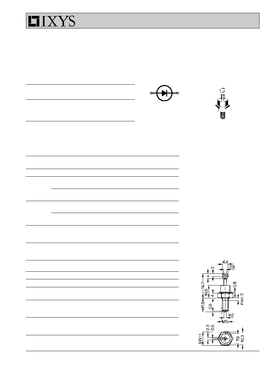
Dimensions in mm (1 mm = 0.0394")
Data according to IEC 60747
IXYS reserves the right to change limits, test conditions and dimensions
DS
9
DSA 9
Rectifier Diode
Avalanche Diode
A
C
DO-203 AA
A = Anode C = Cathode
C
A
M5

© 2000 IXYS All rights reserved
2 - 2
10
-3
10
-2
10
-1
10
0
10
1
0
50
100
150
200
250
300
2
3
4
5 6 7 8 9
1
10
200
400
600
800
100
1000
0.0 0.2 0.4 0.6 0.8 1.0 1.2 1.4 1.6
0
10
20
30
40
50
0
5
10
15
20
0
5
10
15
20
25
0
50
100
150
200
0
10
-3
10
-2
10
-1
10
0
10
1
10
2
10
3
10
4
0
1
2
3
4
5
I
2
t
I
FSM
A
I
F
A
V
F
t
s
t
ms
P
F
W
I
F(AV)M
A
T
amb
∞C
t
s
Z
thJH
K/W
A
2
s
0
50
100
150
200
250
0
5
10
15
20
25
I
F(AV)M
T
c
A
∞C
V
DS
9
DSA 9
Fig. 6 Transient thermal impedance junction to heatsink
Fig. 1 Forward characteristics
Fig. 2 Surge overload current
I
FSM
: crest value, t: duration
Fig. 3 I
2
t versus time (1-10 ms)
R
thJH
for various conduction angles d:
d
R
thJH
(K/W)
DC
3.0
180
∞
3.35
120
∞
3.56
60
∞
4.0
30
∞
4.64
Constants for Z
thJH
calculation:
i
R
thi
(K/W)
t
i
(s)
1
0.095
0.00032
2
0.515
0.0102
3
1.39
0.360
4
1.0
2.30
Fig. 4 Power dissipation versus forward current and ambient temperature
Fig. 5 Max. forward current at case
temperature
typ. lim.
T
VJ
= 180∞C
T
VJ
= 25∞C
50Hz, 80%V
RRM
T
VJ
= 45∞C
T
VJ
= 180∞C
V
R
= 0 V
T
VJ
=45∞C
T
VJ
=180∞C
DC
d = 180∞ sin
d =
120∞
d =
60∞
d =
30∞
30∞
60∞
120∞
180∞
DC
R
thJA
:
8.3 K/W
13 K/W
(CU80x80)
18 K/W
DC
180∞ sin
120∞
60∞
30∞
ase