© 2004 IXYS All rights reserved
1 - 2
DSI 45
420
IXYS reserves the right to change limits, test conditions and dimensions.
Dimensions in mm (1 mm = 0.0394")
V
RSM
V
RRM
Type
V
V
900
800
DSI 45-08A
1300
1200
DSI 45-12A
1700
1600
DSI 45-16A
DSI 45-16AR
V
RRM
= 800-1600 V
I
F(AV)M
= 48 A
Symbol
Conditions
Maximum Ratings
I
F(AV)M
T
C
= 105∞C; 180∞ sine
48
A
I
FSM
T
VJ
= 45∞C;
t = 10 ms (50 Hz), sine
475
A
V
R
= 0 V;
t = 8.3 ms (60 Hz), sine
520
A
T
VJ
= 150∞C;
t = 10 ms (50 Hz), sine
380
A
V
R
= 0 V;
t = 8.3 ms (60 Hz), sine
420
A
I
2
t
T
VJ
= 45∞C;
t = 10 ms (50 Hz), sine
1120
A
2
s
V
R
= 0 V;
t = 8.3 ms (60 Hz), sine
1120
A
2
s
T
VJ
= 150∞C;
t = 10 ms (50 Hz), sine
720
A
2
s
V
R
= 0 V;
t = 8.3 ms (60 Hz), sine
720
A
2
s
T
VJ
-40...+150
∞C
T
VJM
150
∞C
T
stg
-40...+150
∞C
M
d
*
mounting torque
0.8...1.2
Nm
V
ISOL
**
50/60 Hz, RMS, t = 1 minute, leads-to-tab
2500
V~
Weight
typical
6
g
* Verson A only; ** Version AR only
Features
∑
International standard package
∑
Planar glassivated chips
∑ Version AR isolated and
UL registered E153432
∑
Epoxy meets UL 94V-0
Applications
∑
Supplies for DC power equipment
∑
DC supply for PWM inverter
∑
Field supply for DC motors
∑
Battery DC power supplies
Advantages
∑
Space and weight savings
∑
Simple mounting
∑
Improved temperature and power cycling
∑
Reduced protection circuits
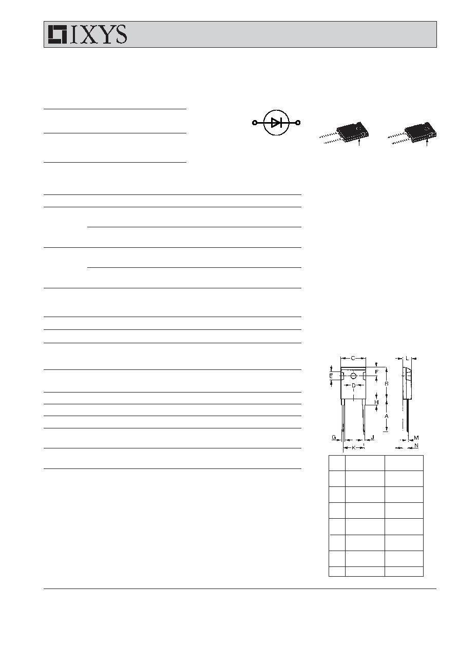
Rectifier Diode
* ISOPLUS 247
TM
without hole
Dim.
Millimeter
Inches
Min.
Max.
Min.
Max.
A
19.81 20.32
0.780
0.800
B
20.80 21.46
0.819
0.845
C
15.75 16.26
0.610
0.640
D*
3.55
3.65
0.140
0.144
E
4.32
5.49
0.170
0.216
F
5.4
6.2
0.212
0.244
G
1.65
2.13
0.065
0.084
H
-
4.5
-
0.177
J
1.0
1.4
0.040
0.055
K
10.8
11.0
0.426
0.433
L
4.7
5.3
0.185
0.209
M
0.4
0.8
0.016
0.031
N
2.2
2.59
0.087
0.102
Symbol
Conditions
Characteristic Values
I
R
T
VJ
= T
VJM
; V
R
= V
RRM
3
mA
V
F
I
F
= 40 A; T
VJ
= 25
∞C
1.18
V
V
T0
For power-loss calculations only
0.8
V
r
T
T
VJ
= T
VJM
8
m
R
thJC
DC current
0.55
K/W
R
thCH
typical
0.2
K/W
Data according to IEC 60747
A = Anode, C = Cathode
TO-247 AD
ISOPLUS 247
TM
Version A
Version AR
C (TAB)
C
A
TAB
C
A
A
C
© 2004 IXYS All rights reserved
2 - 2
DSI 45
420
IXYS reserves the right to change limits, test conditions and dimensions.
0.001
0.01
0.1
1
0
100
200
300
400
500
2
3
4
5 6 7 8 9
1
10
10
2
10
3
10
4
0.0
0.4
0.8
1.2
1.6
0
10
20
30
40
50
60
70
0
10
20
30
40
0
20
40
60
80
100
0
20
40
60
80 100 120 140
0.001
0.01
0.1
1
10
0.0
0.2
0.4
0.6
I
2
t
I
FSM
I
F
A
V
F
t
s
t
ms
P
tot
W
I
d(AV)M
A
T
amb
t
s
K/W
A
2
s
0
20 40 60 80 100 120 140
0
10
20
30
40
50
I
F(AV)M
T
C
A
V
A
∞C
∞C
DSI45
T
VJ
= 45∞C
50Hz, 80% V
RRM
V
R
= 0 V
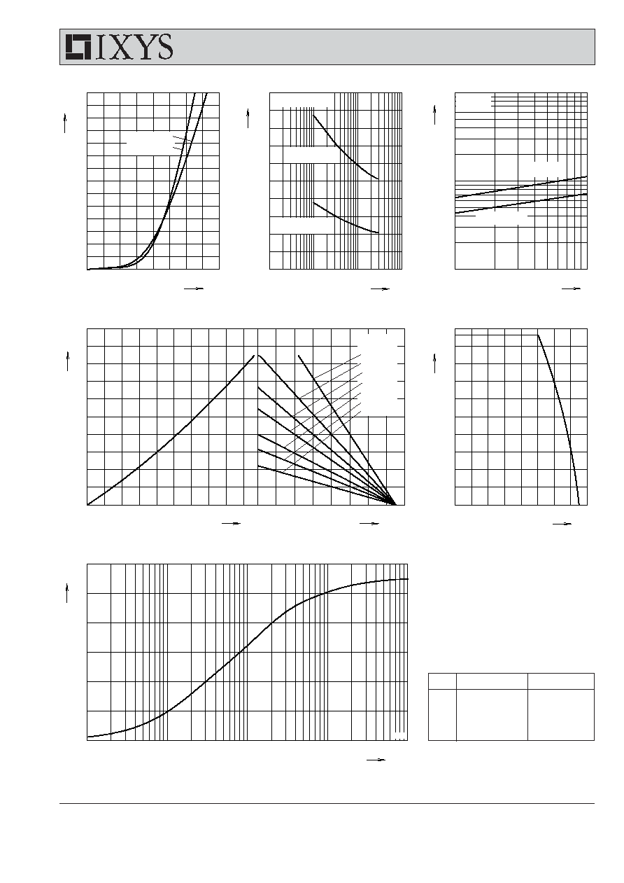
Fig. 1 Forward current versus voltage
drop per diode
Fig. 2 Surge overload current
Fig. 3 I
2
t versus time per diode
Fig. 4 Power dissipation versus direct output current and ambient temperature, sine 180∞
Fig. 5 Max. forward current versus
case temperature
Fig. 6 Transient thermal impedance junction to case
R
thHA
:
0.5 K/W
1.0 K/W
1.5K/W
2.0 K/W
3.0 K/W
4.0 K/W
6.0 K/W
T
VJ
= 150∞C
T
VJ
= 45∞C
T
VJ
=150∞C
T
VJ
= 25∞C
T
VJ
= 150∞C
Z
thJC
Constants for Z
thJC
calculation:
i
R
thi
(K/W)
t
i
(s)
1
0.1633
0.016
2
0.2517
0.118
3
0.0933
0.588
4
0.04167
2.6