© 2001 IXYS All rights reserved
Symbol
Test Conditions Maximum Ratings
V
DSS
T
J
= 25
∞
C to 150
∞
C
75
V
V
GS
Continuous
±
20
V
I
D25
T
C
= 25
∞
C; Note 1
160
A
I
D90
T
C
= 90
∞
C, Note 1
130
A
I
S25
T
C
= 25
∞
C; Note 1, 2
160
A
I
S90
T
C
= 90
∞
C, Note 1, 2
120
A
I
D(RMS)
Package lead current limit
45
A
E
AS
T
C
= 25
∞
C
tbd
mJ
P
D
T
C
= 25
∞
C
300
W
T
J
-55 ... +175
∞
C
T
JM
175
∞
C
T
stg
-55 ... +150
∞
C
T
L
1.6 mm (0.062 in.) from case for 10 s
300
∞
C
V
ISOL
RMS leads-to-tab, 50/60 Hz, t = 1 minute
2500
V~
F
C
Mounting force
11 ... 65 / 2.4 ...11 N/lb
Weight
2
g
Symbol
Test Conditions
Characteristic Values
(T
J
= 25
∞
C, unless otherwise specified)
min.
typ.
max.
R
DS(on)
V
GS
= 10 V, I
D
= 100 A, Note 3
6.5 m
V
GS
= 10 V, I
D
= I
D90
, Note 3
10.2
m
V
GS(th)
V
DS
= V
GS
, I
D
= 2 mA
2
4
V
I
DSS
V
DS
= V
DSS
T
J
= 25
∞
C
20
µ
A
V
GS
= 0 V
T
J
= 125
∞
C
1
mA
I
GSS
V
GS
=
±
20 V
DC
, V
DS
= 0
±
200
nA
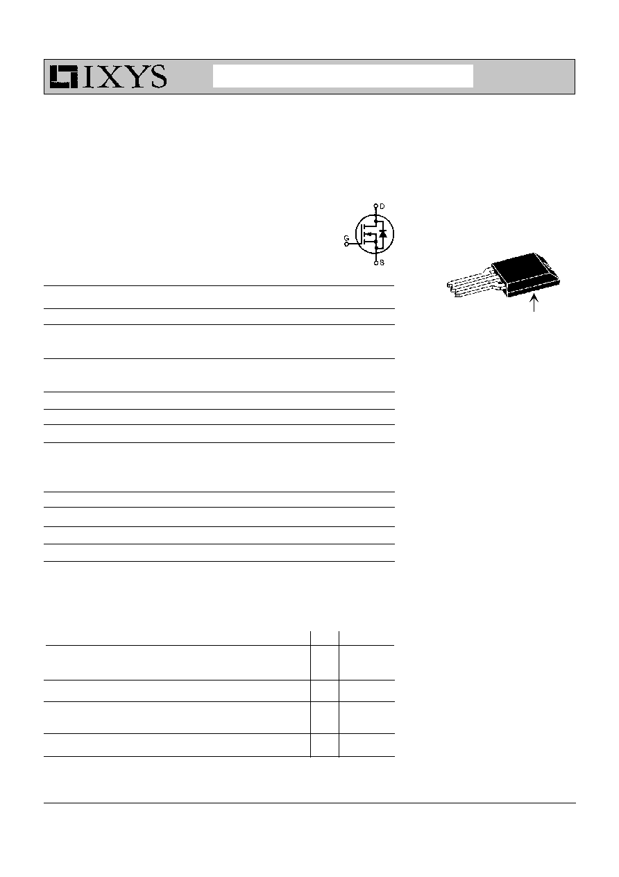
G = Gate,
D = Drain,
S = Source
* Patent pending
Trench Power MOSFET
IXUC160N075
V
DSS
= 75 V
ISOPLUS220
TM
I
D25
= 160 A
Electrically Isolated Back Surface
R
DS(on)
= 6.5 m
98830 (05/01)
ADVANCED TECHNICAL INFORMATION
ISOPLUS 220
TM
Features
l
Silicon chip on Direct-Copper-Bond
substrate
- High power dissipation
- Isolated mounting surface
- 2500V electrical isolation
l
Trench MOSFET
- very low R
DS(on)
- fast switching
- usable intrinsic reverse diode
l
Low drain to tab capacitance(<15pF)
l
Unclamped Inductive Switching (UIS)
rated
Applications
l
Automotive 42V and 12V systems
- electronic switches to replace relays
and fuses
- choppers to replace series dropping
resistors used for motors, heaters, etc.
- inverters for AC drives, e.g. starter
generator
- DC-DC converters, e.g. 12V to 42V, etc.
l
Power supplies
- DC - DC converters
- Solar inverters
l
Battery powered systems
- choppers or inverters for motor control
in hand tools
- battery chargers
Advantages
l
Easy assembly: no screws or isolation
foils required
l
Space savings
l
High power density
G
D
S
Isolated back surface*
IXYS MOSFETS and IGBTs are covered by one or more of the following U.S. patents: 4,835,592
4,881,106
5,017,508
5,049,961
5,187,117
5,486,715
4,850,072
4,931,844
5,034,796
5,063,307
5,237,481
5,381,025
IXYS reserves the right to change limits, test conditions, and dimensions.
Symbol
Test Conditions
Characteristic Values
(T
J
= 25
∞
C, unless otherwise specified)
min.
typ.
max.
Q
g(on)
250
nC
Q
gs
V
GS
= 10 V, V
DS
= 0.5 V
DSS
, I
D
= 100 A
tbd
nC
Q
gd
tbd
nC
t
d(on)
50
ns
t
r
V
GS
= 10 V, V
DS
=40 V,
40
ns
t
d(off)
I
D
= 90 A, R
G
= 4.7
190
ns
t
f
55
ns
R
thJC
0.5
K/W
R
thCH
0.30
K/W
Source-Drain Diode
Characteristic Values
(T
J
= 25
∞
C, unless otherwise specified)
Symbol
Test Conditions
min.
typ.
max.
V
SD
I
F
= 80 A, V
GS
= 0 V
1.1
1.5
V
Note 3
t
rr
I
F
= 90 A, di/dt = -250 A/
µ
s, V
DS
= 0.5 V
DSS
120
ns
Note: 1. MOSFET chip capability
2. Intrinsic diode capability
3. Pulse test, t
300
µ
s, duty cycle d
2 %
IXUC160N075
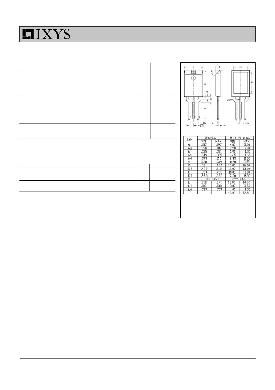
Note: All terminals are solder plated.
1 - Gate
2 - Drain
3 - Source
ISOPLUS220 OUTLINE