© 2000 IXYS All rights reserved
1 - 4
Symbol
Conditions
Maximum Ratings
V
CES
T
J
= 25∞C to 150∞C
1200
V
V
CGR
T
J
= 25∞C to 150∞C; R
GE
= 20 k
W
1200
V
V
GES
Continuous
±20
V
V
GEM
Transient
±30
V
I
C25
T
C
= 25∞C
150
A
I
C90
T
C
= 90∞C
95
A
I
CM
T
C
= 90∞C, t
p
= 1 ms
190
A
RBSOA
V
GE
= ±15 V, T
J
= 125∞C, R
G
= 15
W
I
CM
= 150
A
Clamped inductive load, L = 30 µH
V
CEK
< V
CES
t
SC
V
GE
= ±15 V, V
CE
= V
CES
, T
J
= 125∞C
10
µs
(SCSOA)
R
G
= 15
W
, non repetitive
P
C
T
C
= 25∞C
IGBT
660
W
V
ISOL
50/60 Hz; I
ISOL
£
1 mA
2500
V~
T
J
-40 ... +150
∞C
T
stg
-40 ... +150
∞C
M
d
Mounting torque
1.5/13 Nm/lb.in.
Terminal connection torque (M4)
1.5/13 Nm/lb.in.
Weight
30
g
V
CES
= 1200 V
I
C25
= 150 A
V
CE(sat) typ
= 2.2 V
Features
q
NPT IGBT technology
q
low saturation voltage
q
low switching losses
q
square RBSOA, no latch up
q
high short circuit capability
q
positive temperature coefficient for
easy paralleling
q
MOS input, voltage controlled
q
International standard package
miniBLOC
Advantages
q
Space savings
q
Easy to mount with 2 screws
q
High power density
Typical Applications
q
AC motor speed control
q
DC servo and robot drives
q
DC choppers
q
Uninteruptible power supplies (UPS)
q
Switch-mode and resonant-mode
power supplies
High Voltage IGBT
Short Circuit SOA Capability
Square RBSOA
IXDN 75N120
Symbol
Conditions
Characteristic Values
(T
J
= 25∞C, unless otherwise specified)
min.
typ.
max.
V
(BR)CES
V
GE
= 0 V
1200
V
V
GE(th)
I
C
= 3 mA, V
CE
= V
GE
4.5
6.5
V
I
CES
V
CE
= V
CES
T
J
= 25∞C
4 mA
T
J
= 125∞C
6
mA
I
GES
V
CE
= 0 V, V
GE
= ±
20 V
± 500
nA
V
CE(sat)
I
C
= 75 A, V
GE
= 15 V
2.2
2.7
V
G
E
C
E
E = Emitter
x
,
C = Collector
G = Gate,
E = Emitter
x
x
Either Emitter terminal can be used as
Main or Kelvin Emitter
miniBLOC, SOT-227 B
E153432
G
E
E
C
031
© 2000 IXYS All rights reserved
2 - 4
IXDN 75N120
Symbol
Conditions
Characteristic Values
(T
J
= 25∞C, unless otherwise specified)
min.
typ.
max.
C
ies
5500
pF
C
oes
V
CE
= 25 V, V
GE
= 0 V, f = 1 MHz
750
pF
C
res
330
pF
Q
g
I
C
= 75 A, V
GE
= 15 V, V
CE
= 0.5 V
CES
360
nC
t
d(on)
100
ns
t
r
50
ns
t
d(off)
650
ns
t
f
50
ns
E
on
12.1
mJ
E
off
10.5
mJ
R
thJC
0.19 K/W
R
thCK
Package with heatsink compound
0.1
K/W
Inductive load, T
J
= 125∞C
I
C
= 75 A, V
GE
= ±15 V,
V
CE
= 600 V, R
G
= 15
W
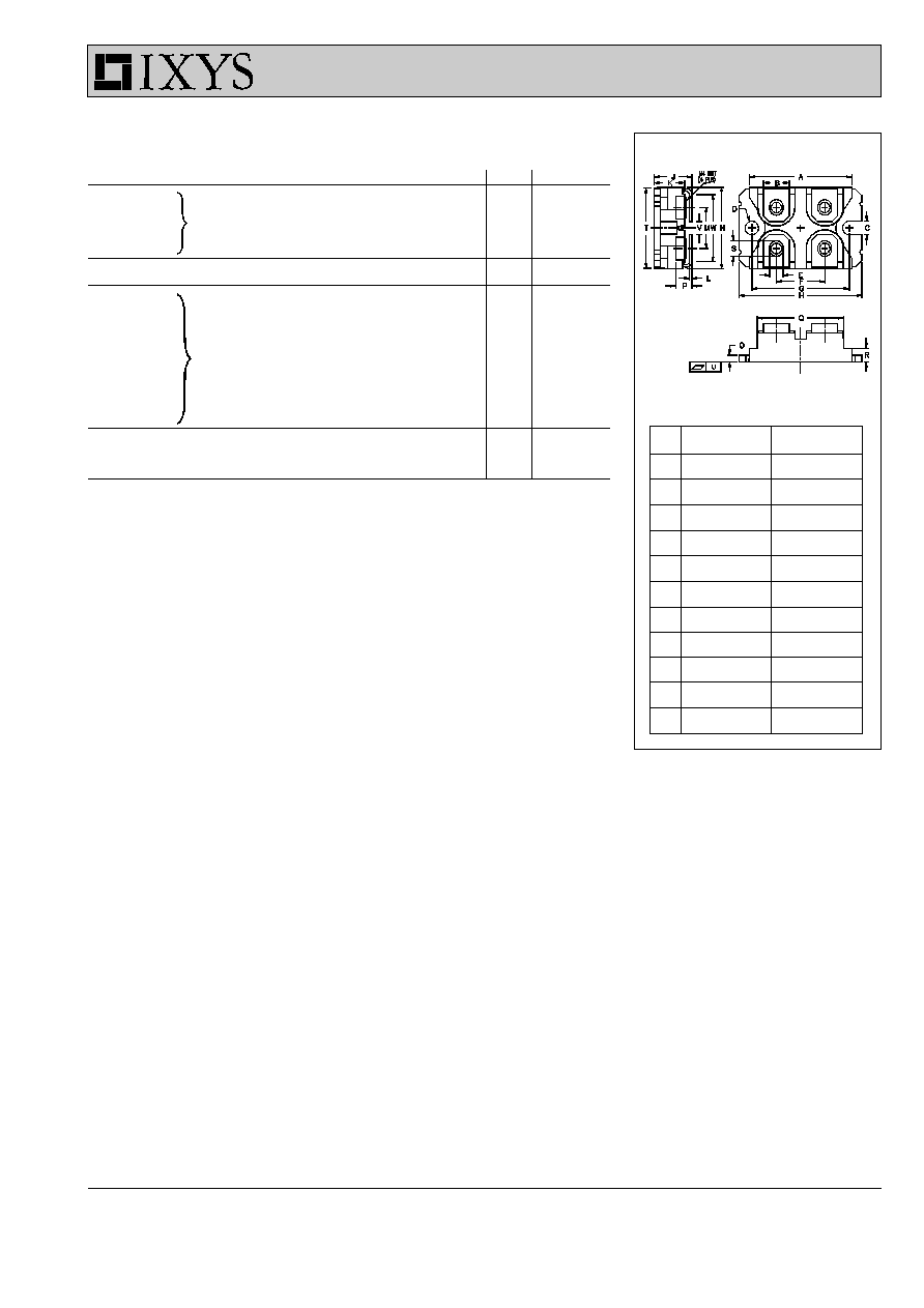
M4 screws (4x) supplied
Dim.
Millimeter
Inches
Min.
Max.
Min.
Max.
A
31.50
31.88
1.240
1.255
B
7.80
8.20
0.307
0.323
C
4.09
4.29
0.161
0.169
D
4.09
4.29
0.161
0.169
E
4.09
4.29
0.161
0.169
F
14.91
15.11
0.587
0.595
G
30.12
30.30
1.186
1.193
H
37.80
38.20
1.489
1.505
J
11.68
12.22
0.460
0.481
K
8.92
9.60
0.351
0.378
L
0.76
0.84
0.030
0.033
M
12.60
12.85
0.496
0.506
N
25.15
25.42
0.990
1.001
O
1.98
2.13
0.078
0.084
P
4.95
5.97
0.195
0.235
Q
26.54
26.90
1.045
1.059
R
3.94
4.42
0.155
0.174
S
4.72
4.85
0.186
0.191
T
24.59
25.07
0.968
0.987
U
-0.05
0.1
-0.002
0.004
V
3.30
4.57
0.130
0.180
W
0.780
0.830
19.81
21.08
miniBLOC, SOT-227 B
© 2000 IXYS All rights reserved
3 - 4
IXDN 75N120
0
200
400
600
800
1000
0
40
80
120
0
100
200
300
0
1
2
3
4
0
50
100
150
200
250
300
0.0
0.5
1.0
1.5
2.0
2.5
3.0
0
25
50
75
100
125
150
175
0
100
200
300
400
0
5
10
15
20
0.0
0.5
1.0
1.5
2.0
2.5
3.0
3.5
0
25
50
75
100
125
150
175
13V
11V
T
J
= 25∞C
V
GE
=17V
T
J
= 125∞C
V
CE
= 600V
I
C
= 75A
15V
5
6
7
8
9
10
11
0
25
50
75
100
125
150
13V
11V
V
GE
=17V
15V
V
CE
= 20V
T
J
= 25∞C
9V
9V
V
CE
V
A
I
C
V
CE
A
I
C
V
V
V
V
GE
V
F
A
I
C
A
I
F
nC
Q
G
-di/dt
V
V
GE
A
I
RM
t
rr
ns
A/
m
s
IXDN75N120
T
J
= 125∞C
V
R
= 600V
I
F
= 75A
T
J
= 25∞C
T
J
= 125∞C
I
RM
t
rr
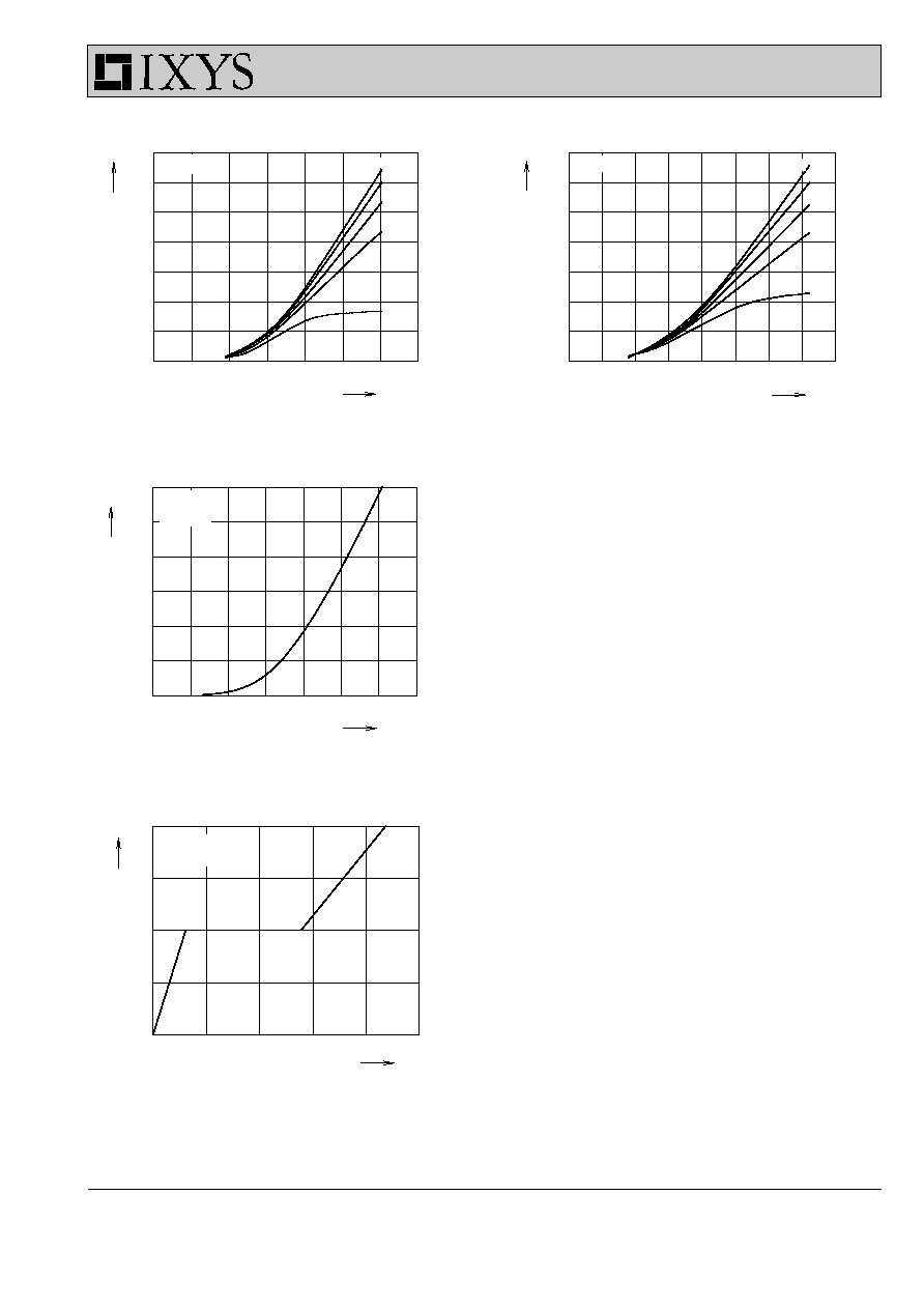
Fig. 1 Typ. output characteristics
Fig. 2 Typ. output characteristics
Fig. 3 Typ. transfer characteristics
Fig. 4 Typ. turn on gate charge
© 2000 IXYS All rights reserved
4 - 4
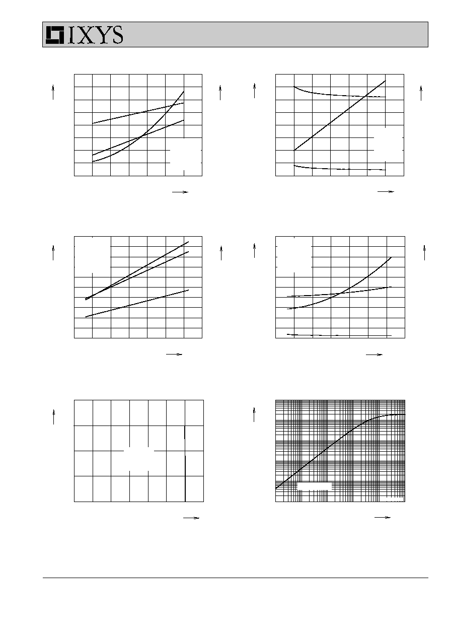
Fig. 5 Typ. turn on energy and switching
Fig. 6 Typ. turn off energy and switching
times versus collector current
times versus collector current
Fig. 7 Typ. turn on energy and switching
Fig.8
Typ. turn off energy and switching
times versus gate resistor
times versus gate resistor
Fig. 9 Reverse biased safe operating area
Fig. 10 Typ. transient thermal impedance
RBSOA
0
50
100
150
0
10
20
30
40
0
40
80
120
160
0
50
100
150
0
5
10
15
20
0
200
400
600
800
0.00001
0.0001
0.001
0.01
0.1
1
0.00001
0.0001
0.001
0.01
0.1
1
0
8
16
24
32
40
48
56
0
5
10
15
20
25
0
400
800
1200
1600
2000
0
8
16
24
32
40
48
56
0
5
10
15
20
25
0
40
80
120
160
200
single pulse
V
CE
= 600V
V
GE
= ±15V
R
G
= 15
W
T
J
= 125∞C
IXDN75N120
V
CE
= 600V
V
GE
= ±15V
I
C
= 75A
T
J
= 125∞C
0
200
400
600
800
1000 1200
0
50
100
150
200
R
G
= 15
W
T
J
= 125∞C
V
CEK
< V
CES
V
CE
= 600V
V
GE
= ±15V
R
G
= 15
W
T
J
= 125∞C
E
on
V
CE
= 600V
V
GE
= ±15V
I
C
= 75A
T
J
= 125∞C
t
d(on)
t
r
E
off
t
d(off)
t
f
E
on
t
d(on)
t
r
E
off
t
d(off)
t
f
I
C
A
I
C
A
mJ
E
off
mJ
E
on
ns
t
ns
t
R
G
W
R
G
W
V
CE
t
s
mJ
E
on
mJ
E
off
ns
t
ns
t
I
CM
K/W
Z
thJC
V
A
IXDN 75N120