
© 2000 IXYS All rights reserved
1 - 2
Symbol
Test Conditions
Maximum Ratings
I
TRMS
T
VJ
= T
VJM
A
I
TAVM
T
C
= 85
∞
C; 180
∞
sine
A
I
TSM
T
VJ
= 45
∞
C;
t = 10 ms (50 Hz)
A
V
R
= 0
t = 8.3 ms (60 Hz)
A
T
VJ
= T
VJM
t = 10 ms (50 Hz)
A
V
R
= 0
t = 8.3 ms (60 Hz)
A
Ú
i
2
dt
T
VJ
= 45
∞
C
t = 10 ms (50 Hz)
A
2
s
V
R
= 0
t = 8.3 ms (60 Hz)
A
2
s
T
VJ
= T
VJM
t = 10 ms (50 Hz)
A
2
s
V
R
= 0
t = 8.3 ms (60 Hz)
A
2
s
(di/dt)
cr
T
VJ
= T
VJM
repetitive, I
T
=
A
A/
m
s
f = 50 Hz, t
P
= 200
m
s
V
D
= 2/3 V
DRM
I
G
=
A,
non repetitive, I
T
= I
TAVM
A/
m
s
di
G
/dt =
A/
m
s
(dv/dt)
cr
T
VJ
= T
VJM
; V
DR
= 2/3 V
DRM
V/
m
s
R
GK
=
•
; method 1 (linear voltage rise)
P
GM
T
VJ
= T
VJM
t
P
=
30
m
s
W
I
T
= I
TAVM
t
P
= 300
m
s
W
P
GAV
W
V
RGM
V
T
VJ
∞
C
T
VJM
∞
C
T
stg
∞
C
V
ISOL
50/60 Hz, RMS
t = 1 min
V~
I
ISOL
£
1 mA
t = 1 s
V~
M
d
Mounting torque (M5)
Nm/lb.in.
Terminal connection torque (M5)
Nm/lb.in.
Weight
Typical including screws
g
I
TRMS
= 2x 180 A
I
TAVM
= 2x 10⁴ A
V
RRM
= 2000-2200 V
V
RSM
V
RRM
Type
V
DSM
V
DRM
V
V
2100
2000
MCC 94-20io1 B
MCD 94-20io1 B
2300
2200
MCC 94-22io1 B
MCD 94-22io1 B
Data according to IEC 60747 and refer to a single thyristor/diode unless otherwise stated.
IXYS reserves the right to change limits, test conditions and dimensions
1700
1800
180
104
1540
1640
14450
13500
11850
11300
250
150
0.45
500
0.45
1000
10
5
0.5
10
2.5-4.0/22-35
2.5-4.0/22-35
90
-40 ...125
125
-40 ...125
3000
3600
Features
q
International standard package,
JEDEC TO-240 AA
q
Direct Copper Bonded Al
2
O
3
-ceramic
base plate
q
Planar passivated chips
q
Isolation voltage 3600 V~
q
UL registered, E 72873
q
Gate-cathode twin pins for version 1B
Applications
q
DC motor control
q
Softstart AC motor controller
q
Light, heat and temperature control
Advantages
q
Space and weight savings
q
Simple mounting with two screws
q
Improved temperature and power
cycling
q
Reduced protection circuits
839
MCC 94
MCD 94
High Voltage Thyristor Module
High Voltage Thyristor/Diode Modules
6
7
4
5
3
2
1
TO-240 AA
MCD
MCC
3
6 7 1
5 4 2
3
1
5 4 2
© 2000 IXYS All rights reserved
2 - 2
Optional accessories for module-type MCC 94 version 1 B
Keyed gate/cathode twin plugs with wire length = 350 mm, gate = yellow, cathode = red
Type ZY 200L
(L = Left for pin pair 4/5)
UL 758, style 1385,
Type ZY 200R
(R = right for pin pair 6/7)
CSA class 5851, guide 460-1-1
1.5
1.6
100
200
0.22
0.11
0.42
0.21
12.7
9.6
50
15
0.85
3.2
0.25
10
150
Dimensions in mm (1 mm = 0.0394")
MCC 94
MCD 94
Symbol
Test Conditions
Characteristic Values
I
RRM
, I
DRM
T
VJ
= T
VJM
; V
R
= V
RRM
mA
V
T
I
T
= 300 A; T
VJ
= 25
∞
C
1.74
V
V
T0
For power-loss calculations only (T
VJ
= T
VJM
)
V
r
T
m
W
V
GT
V
D
= 6 V;
T
VJ
= 25
∞
C
V
T
VJ
= -40
∞
C
V
I
GT
V
D
= 6 V;
T
VJ
= 25
∞
C
mA
T
VJ
= -40
∞
C
mA
V
GD
T
VJ
= T
VJM
; V
D
= 2/3 V
DRM
V
I
GD
T
VJ
= T
VJM
; V
D
= 2/3 V
DRM
mA
I
L
T
VJ
= 25
∞
C; V
D
= 6 V; t
P
= 30
m
s
200
mA
di
G
/dt = 0.45 A/
m
s; I
G
= 0.45 A
I
H
T
VJ
= 25
∞
C; V
D
= 6 V; R
GK
=
•
mA
t
gd
T
VJ
= 25
∞
C; V
D
= 1/2 V
DRM
2
m
s
di
G
/dt = 0.45 A/
m
s; I
G
= 0.45 A
t
q
T
VJ
= T
VJM
; V
R
= 100 V; V
D
= 2/3 V
DRM
; t
P
= 200
m
s
typ.
185
m
s
dv/dt = 20 V/
m
s; I
T
= 150 A; -di/dt = 10 A/
m
s
Q
S
T
VJ
= T
VJM
170
m
C
I
RM
-di/dt = 6 A/
m
s; I
T
= 50 A
45
A
R
thJC
per thyristor; DC current
K/W
per module
K/W
R
thJK
per thyristor; DC current
K/W
per module
K/W
d
S
Creeping distance on surface
mm
d
A
Creepage distance in air
mm
a
Maximum allowable acceleration
m/s
2
10
100
1000
1
10
100
1000
10
0
10
1
10
2
10
3
10
4
0.1
1
10
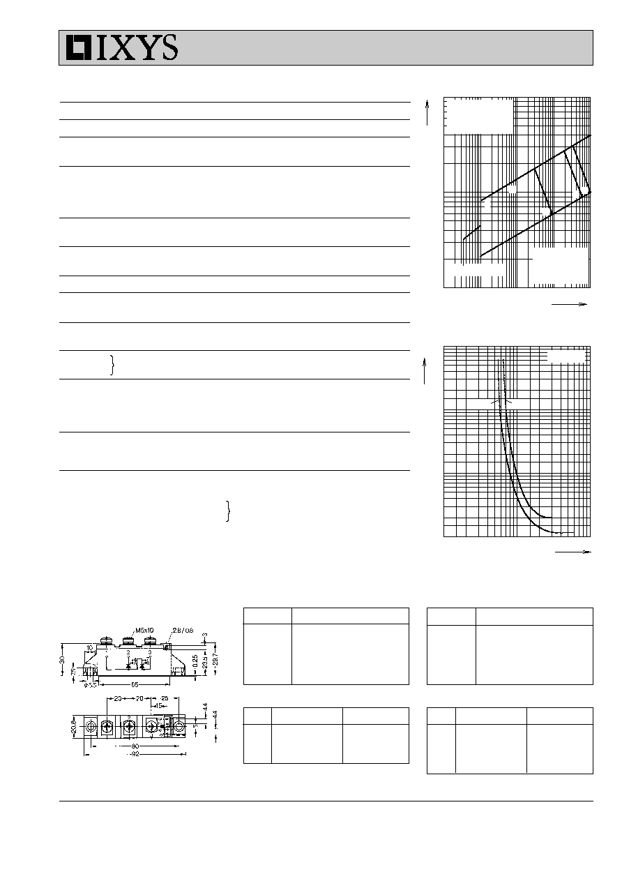
I
G
V
G
mA
mA
I
G
1: I
GT
, T
VJ
= 125
∞
C
2: I
GT
, T
VJ
= 25
∞
C
3: I
GT
, T
VJ
= -40
∞
C
µ
s
t
gd
V
4: P
GAV
= 0.5 W
5: P
GM
= 5 W
6: P
GM
= 10 W
I
GD
, T
VJ
= 125
∞
C
3
4
2
1
5
6
Limit
typ.
T
VJ
= 25
∞
C
Fig. 1 Gate trigger characteristics
Fig. 2 Gate trigger delay time
R
thJC
for various conduction angles d:
d
R
thJC
(K/W)
DC
0.22
180
∞
0.23
120
∞
0.25
60
∞
0.27
30
∞
0.28
Constants for Z
thJC
calculation:
i
R
thi
(K/W)
t
i
(s)
1
0.0066
0.0019
2
0.0678
0.0477
3
0.1456
0.344
R
thJK
for various conduction angles d:
d
R
thJK
(K/W)
DC
0.42
180
∞
0.43
120
∞
0.45
60
∞
0.47
30
∞
0.48
Constants for Z
thJK
calculation:
i
R
thi
(K/W)
t
i
(s)
1
0.0066
0.0019
2
0.0678
0.0477
3
0.1456
0.344
4
0.2
1.32