
© 2003 IXYS All rights reserved
1 - 2
IXYS reserves the right to change limits, Conditions and dimensions.
342
VBE 60-06A
Advanced Technical Information
Single Phase Rectifier Bridge
with Fast Recovery Epitaxial Diodes (FRED)
Features
∑ International standard package miniBLOC
∑ Isolation voltage 2500 V~
∑ single Phase Rectifier Bridge with FREDs
∑ Planar passivated chips
∑ Very short recovery time
∑ Extremely low switching losses
∑ Low I
RM
-values
∑ Soft recovery behaviour
Applications
∑ Supplies for DC power equipment
∑ Input and output rectifiers for high
frequency
∑ Battery DC power supplies
∑ Field supply for DC motors
Advantages
∑ Avalanche voltage rated for reliable
operation
∑ Soft reverse recovery for low EMI/RFI
∑ Low I
RM
reduces:
- Power dissipation within the diode
- Turn-on loss in the commutating switch
Dimensions see Outlines.pdf
Pulse test:
for resistive load at bridge output.
Pulse Width = 5 ms, Duty Cycle < 2.0 %
Pulse Width = 300
µ
s, Duty Cycle < 2.0 %
I
dAV
= 60 A
V
RRM
= 600 V
t
rr
= 35 ns
V
RSM
V
RRM
Type
V
V
600
600
VBE 60-06A
Symbol
Conditions
Maximum Ratings
I
FRMS
70
A
I
dAV
rect., d = 0.5; T
C
= 90∞C
60
A
I
FSM
T
VJ
= 45∞C; V
R
= 0;
250
A
I
2
t
t
p
= 10 ms (50 Hz), sine
315
A
2
s
E
AS
T
VJ
= 25∞C; non-repetitive
0.2
mJ
I
AS
= 1.3 A; L = 180 µH
I
AR
V
A
= 1.5∑V
R
typ.; f = 10 kHz; repetitive
0.1
A
T
VJ
-40...+150
∞C
T
VJM
150
∞C
T
stg
-40...+150
∞C
P
tot
T
C
= 25∞C
140
W
V
ISOL
50/60 Hz, RMS
2500
V~
I
ISOL
1 mA
M
d
mounting torque (M4)
1.1-1.5/9-13
Nm/lb.in.
terminal connection torque (M4)
1.1-1.5/9-13
Nm/lb.in.
Weight
typical
30
g
Symbol
Conditions
Characteristic max. Values
I
R
V
R
= V
RRM
; T
VJ
= 25∞C
0.15
mA
V
R
= V
RRM
; T
VJ
= 125∞C
1
mA
V
F
I
F
= 30 A;
T
VJ
= 125∞C
1.26
V
T
VJ
= 25∞C
1.54
V
R
thJC
1.15
K/W
R
thCH
typ.
0.1
K/W
t
rr
I
F
= 1 A; -di/dt = 200 A/µs;
typ.
35
ns
V
R
= 30 V; T
VJ
= 25∞C
I
RM
V
R
= 100 V; I
F
= 50 A; -di
F
/dt = 100 A/µs
typ.
5.5
A
T
VJ
= 100∞C
+
≠
~
~
~
≠
miniBLOC, SOT-227 B
~
+
Data according to IEC 60747 and per diode unless otherwise specified
© 2003 IXYS All rights reserved
2 -2
IXYS reserves the right to change limits, Conditions and dimensions.
342
VBE 60-06A
Advanced Technical Information
200
600
1000
0
400
800
70
80
90
100
110
120
130
0.0001
0.001
0.01
0.1
1
0.001
0.01
0.1
1
10
0
40
80
120
160
0.0
0.5
1.0
1.5
2.0
K
f
T
VJ
∞C
-di
F
/dt
t
s
K/W
0
200
400
600
800
1000
0
5
10
15
20
0.0
0.3
0.6
0.9
1.2
V
FR
di
F
/dt
V
200
600
1000
0
400
800
0
10
20
30
40
50
100
1000
0
500
1000
1500
2000
2500
3000
0.0
0.5
1.0
1.5
2.0
0
10
20
30
40
50
60
70
I
RM
Q
r
I
F
A
V
F
-di
F
/dt
-di
F
/dt
A/
µ
s
A
V
nC
A/
µ
s
A/
µ
s
t
rr
ns
t
fr
Z
thJC
A/
µ
s
µ
s
DSEP 2x31-06A
I
F
= 60A
I
F
= 30A
I
F
= 15A
T
VJ
= 100∞C
V
R
= 300V
T
VJ
= 100∞C
I
F
= 30A
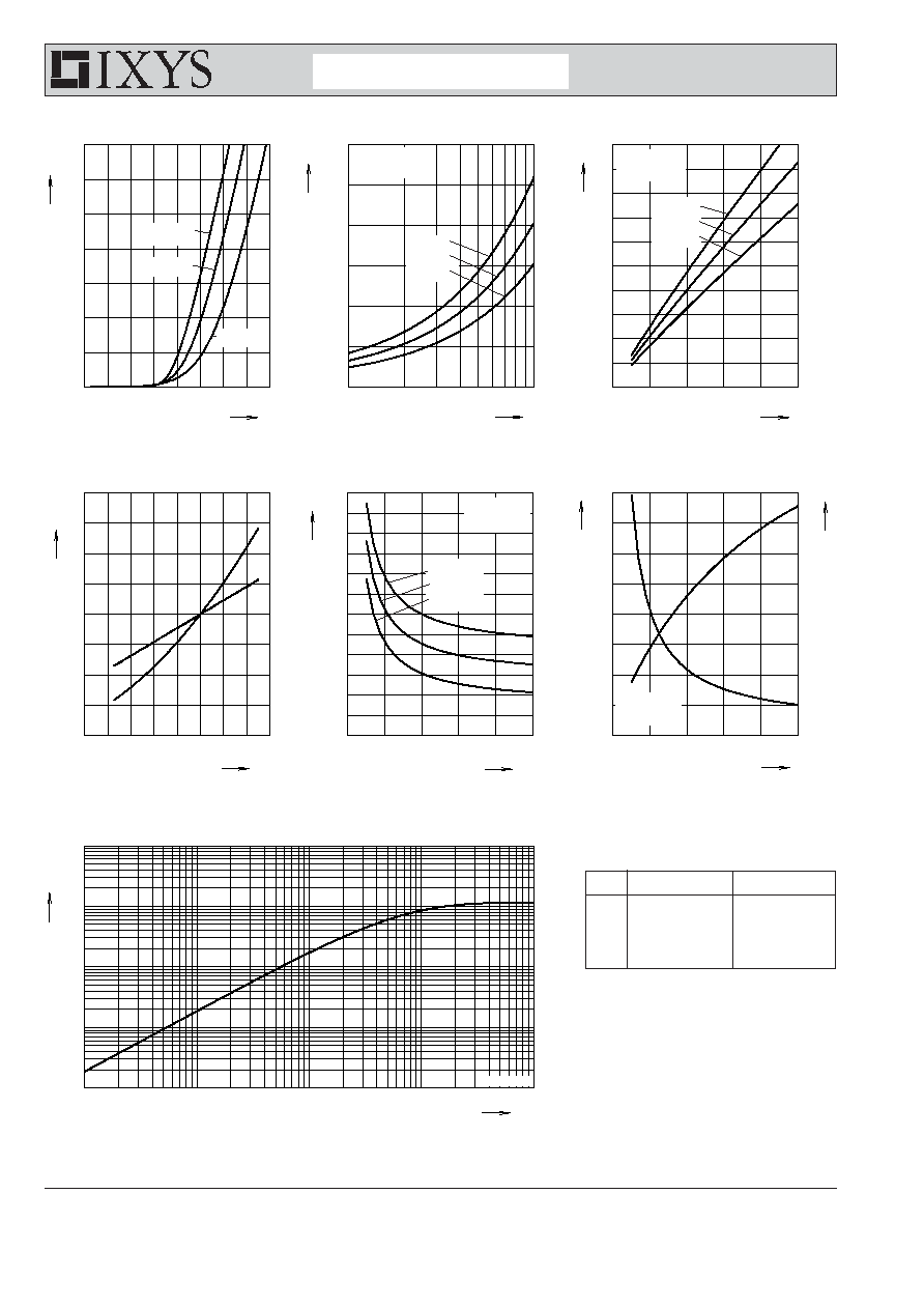
Fig. 3 Peak reverse current I
RM
versus -di
F
/dt
Fig. 2 Reverse recovery charge Q
r
versus -di
F
/dt
Fig. 1 Forward current I
F
versus V
F
T
VJ
= 100∞C
V
R
= 300V
T
VJ
= 100∞C
V
R
= 300V
I
F
= 60A
I
F
= 30A
I
F
= 15A
Q
r
I
RM
Fig. 4 Dynamic parameters Q
r
, I
RM
versus T
VJ
Fig. 5 Recovery time t
rr
versus -di
F
/dt
Fig. 6 Peak forward voltage V
FR
and t
fr
versus di
F
/dt
I
F
= 60A
I
F
= 30A
I
F
= 15A
t
fr
V
FR
Fig. 7 Transient thermal resistance junction to case
T
VJ
=25∞C
T
VJ
=100∞C
T
VJ
=150∞C
NOTE: Fig. 2 to Fig. 6 shows typical values
Constants for Z
thJC
calculation:
i
R
thi
(K/W)
t
i
(s)
1
0.436
0.0055
2
0.482
0.0092
3
0.117
0.0007
4
0.115
0.0418