FEATURES
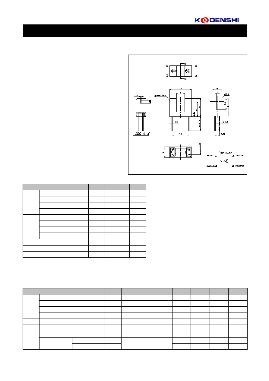
∑ PWB direct mount type
APPLICATIONS
∑ Printers
∑ Copiers
∑ A T M
∑ Ticket Vending Machines
ABSOLUTE MAXIMUM RATINGS
(Ta=25
)
ELECTRO-OPTICAL CHARACTERISTICS
(Ta=25
)
1/2
C
T
f=1KHz
Parameter
Reverse Current
V
0.4
-
-
Unit
DESCRIPTION
a high sensitivity phototransistor.
∑ GAP : 5.0mm
∑ Easy to mount
MAX.
V
R
=5V
1.7
-
TYP.
1.2
-
-
KPI-L06
KPI-L06 combines a high-output GaAs IRED with
DIMENSIONS
The photointerrupter high-performance standard type
100
V
µA
10
nA
nm
-
-
P
F
940
-
25
-
-
MIN.
µs
µs
-
5
-
5
-
-
15
?
P
tr
tf
V
CE(SAT)
I
CEO
I
F
=20mA, I
C
=0.1mA
V
CC
=5V, I
C
=2mA,
R
L
=100
-
Coupled
Rise Time
Response Time
Fall Time
Collector Emitter Saturation Voltage
1
60
Dark Current
Input
Peak Wavelength
Output
Capacitance
Forward Voltage
I
F
=20mA
V
CE
=5V, 0 Lux
Symbol
Input
Unit
100
mW
mA
V
A
Rating
5
-20 ~ +85
100
Emitter Collector Voltage
V
V
30
5
V
ECO
Forward Current
Reverse Voltage
Pulse Forward Current
*1
Power Dissipation
Collector Current
Storage Temperature
*2
T
STG
Collector Power Dissipation
Output
Collector Emitter Voltage
T
SOL
Soldering Temperature
*3
*2. No icebound or dew
I
F
V
R
I
FP
P
C
V
CEO
P
D
40
mA
I
R
Symbol
V
F
Conditions
I
F
=20mA
260
-30 ~ +85
mW
Parameter
*1. Pulse width : tw
100µsec.period : T=10msec
*3. For MAX. 5 seconds at the position of 1mm from the package
Photointerrupter(Transmissive)
Operating Temperature
*2
T
OPR
I
C
mA
Light Current
I
L
V
CE
=5V, I
F
= 20mA (Non-shading)
0.5
-
Photointerrupter(Transmissive)
2/2
KPI-L06
P
ow
e
r
d
i
s
s
i
p
a
t
i
o
n
(
P
)
F
o
rwa
r
d
c
urrent
(I
F
)
R
e
l
a
t
i
ve
l
i
g
h
t
c
u
r
r
e
n
t
(
I
)
Re
s
p
o
n
s
e
t
i
m
e
t
r
,
tf
Input
Moving distance(L)
10
10
L
Road Resistance(R )
10
tf
2
10
3
10
1
2
tr
4
( )
0
-2
50
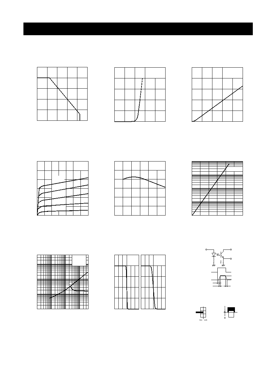
Method of measuring position
detection characteristic
0
0
+2
-2
+2
0
(mm)
Optical Axis(X)
Output
td
tr
O
p
t
i
c
a
l
A
x
i
s
(
Y)
tf
90%
10%
Ambient temperature(Ta)
Forward voltage(V )
R
e
l
a
t
i
ve
l
i
g
h
t
c
u
r
r
e
n
t
(
I
)
100
()
10
I =10mA
V =5V
Ta=25∞
3
F
CC
C
100
(%) X
L
0
0
-20
50
50
0
L
(%)
Ambient temperature(Ta)
40
20
0
60
80
()
0
0
0.5
50
C
o
l
l
e
c
t
or
d
a
r
k
c
u
r
r
e
n
t
(
I
)
Response time measurement circuit
Ambient temperature(Ta)
C
Ta=25∞
I =10mA
F
CC
V =5V
Y
C
Ta=25∞
I =10mA
F
V =5V
CC
Input
I
C
20
0
40
()
60
10
-1
10
0
40
20
60
0
10
1
CC
V
R
L
V
OUT
()
100
80
I =20mA
F
CE
V =5V
(nA)
CEO
10
2
1.0
1.5
(V)
2.0
F
V =10V
CE
()
100
C
()
100
Ta=25∞
C
L
i
g
h
t
C
u
r
r
e
n
t
(
I
)
I =30mA
I =20mA
I =10mA
Collector-Emitter Voltage(V )
2
2
4
0
0
1
CE
F
F
8
10
6
F
12 (V)
I =40mA
I =50mA
L
5
3
4
()
Ta=25∞
F
F
C
L
i
g
h
t
C
u
r
r
e
n
t
(
I
)
Forward Current(I )
0
1
2
0
10
20
F
(mA)
40
30
()
L
3
4
V =5V
Ta=25∞
CE
C
0
0
50
1 00
()
60
Ambient temperature(Ta)
20
40
80 ()
Collector power dissipation Vs.
Ambient temparature
Forward current Vs.
Forward voltage
Light current Vs.
Forward current
Light current Vs.
Collentor-Emitter voltage
Relative light current Vs.
Ambient temperature
Dark current Vs.
Ambient temperature
Switching time Vs.
Load resistance
Relative light current Vs.
Moving distance
Power dissipartion( P
C
)
Forward current( I
F
)
Light Current( I
L
)
Ambient temperature(Ta)
Forward voltage( V
F
)
Forward Current( I
F
)
Light Current( I
L
)
Relative light current( I
L
)
Response time tr, tf
Relative light current( I
L
)
Collector-Emitter Voltage( V
CE
)
Ambient temperature( Ta )
Load Resistance( R
L
)
Moving distance( L )
detection characteristic
Method of measuring position
Response time measurement circuit
Optical Axis(X)
Optical Axis(Y)
Collector dark current( I
CEO
)
Ambient temperature( Ta )