Optic receiver module
[Ta=25
]
[Ta=25 , Vcc=5.0V]
*1. It specifies the maxmum distance between emitter and detector that the output wave form satisfies the standard under the conditions
below against the standard transmitter.
1) Measuring place
: Indoor without extreme reflection of light
2) Ambient light source : Detecting surface illumination shall be irradiate 200
±
50lx under ordinary white fluorescence lamp without
high frequency lightning
3) Standard transmitter : Burst wave of standard transmitter shall be arranged to 50mVP-P under the measuring circuit
1/2
Model No. B.P.F Center Frequency(
)
Soldering Temperature Tsol 260
Storage Temperature Tstg -20 ~ +75
Operating Temperature Topr -10 ~ +60
KSM-40 N
Parameter
Symbol
Ratings
Unit
Supply Voltage Vcc 6.0 V
Output Form
KSM-405N
56.9
Parameter
Symbol
Condition
Active Low Output
Min.
Typ.
KSM-401N
40.0
KSM-402N
36.7
KSM-403N
37.9
KSM-404N
32.7
Max.
Unit
Recommended Supply Voltage
Vcc
(Max 5 sec)
4.5
5
5.5
V
Current Consumption Icc
No signal input - 1.2 2.5 mA
Peak Wavelength *1
p - 940 - nm
B.P.F Center Frequency fo - 37.9 -
4.5
L m
7 - -
5 -
±
30
°
-
Transmission Distance *1
250
±
50lx
±
0
°
High level Output voltage *1
V
OH
30cm over
V
Low level Output voltage *1 V
OL
the ray axis - 0.1 0.5 V
5.0
-
High level Output Pulse Width *1 T
WH
Burst wave=600
500 600 700
Low level Output Pulse Width *1 T
WL
Period = 1.2
500 600 700
The KSM-40 N consist of a PIN Photodiode of high
speed and a preamplifier IC in the package as an receiver
for Infrared remote control systems
Features
Small size SMD package
Supply-voltage range : 4.5V to 5.5V
Shielded against electrical field disturbance
Enhanced immunity against ambient light disturbances
Available for carrier frequencies between 32.7KHz to 56.9KHz
TTL and CMOS compatible
Applications
Audio & Video Applications (TV, VTR, Audio, DVDP, CDP)
Home Appliances (Air conditioner, Computer, Camcoder)
Wireless Toys
Remote Control Equipment
Maximum Ratings
Electro-Optical Characteristics
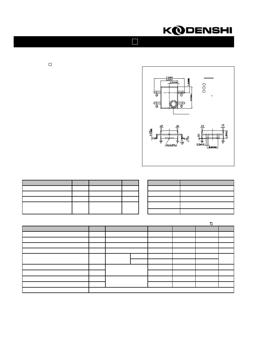
DIMENSIONS
B.P.F Center Frequency
(Unit : mm)
LASER MARKING
NOTE
1. PIN CONFIG.
2. G.T : 0.3
1 Vcc
2 Vout
3 GND
Optic receiver module
*
1 Recommended Circuit Description
1) Transmitter(IRED) drive current
: IFP = 300mA
P-P
~ 600mA
P-P
2) R-C Decoupling Filter with Lower Cut-off Frequency
: R=100
, C=47
fc = 1/2
RC = 33.9Hz
3) External pull-up resistor(optional)
: 10
k
over
2/2
KSM-
40N
Measuring Method
[Ta=25
]
Transmitter output
Carrier Frequency(fo)
Duty50%
Remocon output pulse
T
WL
T
HL
600us 600us
Standard
Tansmitter
25Cm
10
Vout
10
1
0
+5V
Transmitter
Arrival Distance : L
Vout
Vcc
GND
OSC
: Indicates horizontal and
vertical directions
Output Pulse Width
Standard Transmitter
Test Method of Transmission Distance
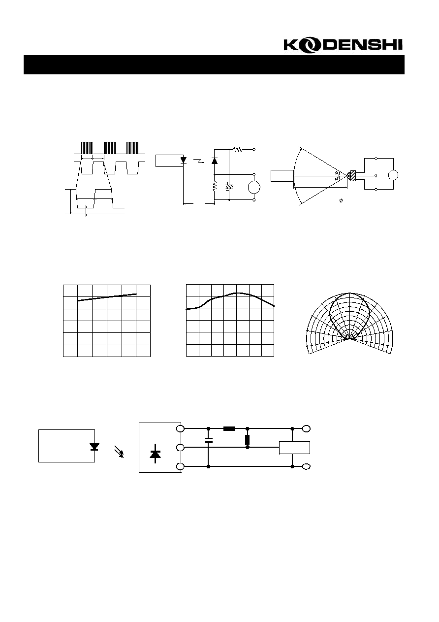
Typical Characteristics Curve
[Ta=25
]
Relative reception distance Vs.
Supply voltage
Relative reception distance Vs.
Ambient temperature
Radiant pattern
Standard Application Circuit with R-C Decoupling Filter
Transmitter
Vcc
GND
Vcc
GND
Vout
micom
C
R
Receiver
Module
Rp
V
H
V
L
0
20
40
60
80
100
120
-10 0 10 20 30 40 50
Ambient temperature Ta
R
e
l
a
t
i
v
e
r
e
c
e
p
t
i
o
n
d
i
s
t
a
n
c
e
[%]
[]
0
20
40
60
80
100
120
4.5
5.0 5.5
Supply voltage Vcc
R
e
l
a
t
i
v
e
r
e
c
e
p
t
i
o
n
d
i
s
t
a
n
c
e
[%]
[V]
Relative Sensitivity [%]
-100°
-80°
-60°
-40°
-20°
0°
20°
40°
60°
80°
100°
0
50
100
50
100