 | –≠–ª–µ–∫—Ç—Ä–æ–Ω–Ω—ã–π –∫–æ–º–ø–æ–Ω–µ–Ω—Ç: TV1820FM | –°–∫–∞—á–∞—Ç—å:  PDF PDF  ZIP ZIP |
TV18..F
1/8
APPLICATIONS
s
Induction Heating
s
A.C. Motor Drives
s
Snubber Diode
s
Welding
s
High Frequency Rectification
s
UPS
FEATURES
s
Thermal Fatigue Free Pressure Contact
s
High Surge Capability
s
Low Recovery Charge
VOLTAGE RATINGS
KEY PARAMETERS
V
RRM
2500V
I
F(AV)
200A
I
FSM
3500A
Q
r
240
µ
C
t
rr
2.0
µ
s
2500
2400
2200
2000
TV18 25F M or K
TV18 24F M or K
TV18 22F M or K
TV18 20F M or K
Conditions
V
RSM
= V
RRM
+ 100V
For 3/4" 16 UNF thread, add suffix K, e.g. TV18 25FK.
For M16 thread, add suffix M, e.g. TV18 25FM.
For stud anode add 'R' to type number, e.g. TV18 25FMR.
Type Number
Repetitive Peak
Reverse Voltage
V
RRM
V
Outline type codes: DO9.
See Package Details for further information.
CURRENT RATINGS
Symbol
Parameter
Conditions
Units
Max.
I
F(AV)
Mean forward current
I
F(RMS)
RMS value
Half wave resistive load, T
case
= 65
o
C
200
A
T
case
= 65
o
C
320
A
TV18..F
Fast Recovery Diode
Replaces March 1998 version, DS4211-2.2
DS4211-3.0 January 2000

TV18..F
2/8
SURGE RATINGS
Conditions
Max.
Units
3.5
kA
61 x 10
3
A
2
s
I
2
t for fusing
I
2
t
Surge (non-repetitive) forward current
I
FSM
Parameter
Symbol
10ms half sine; with 0% V
RRM,
T
j
= 150
o
C
2.8
kA
39.2x 10
3
A
2
s
I
2
t for fusing
I
2
t
Surge (non-repetitive) forward current
I
FSM
10ms half sine; with 50% V
RRM,
T
j
= 150
o
C
THERMAL AND MECHANICAL DATA
dc
Conditions
Max.
Units
o
C/W
-
0.06
Thermal resistance - case to heatsink
R
th(c-h)
Thermal resistance - junction to case
R
th(j-c)
Mounting torque 35.0Nm
with mounting compound
Symbol
Parameter
-
0.16
o
C/W
Min.
t
rr
50
Symbol
Typ.
Units
Parameter
V
FM
Forward voltage
I
RRM
Peak reverse current
Reverse recovery time
Q
RA1
Recovered charge (50% chord)
I
RM
Reverse recovery current
K
Soft factor
V
TO
Threshold voltage
r
T
Slope resistance
V
FRM
Forward recovery voltage
di/dt = 1000A/
µ
s, T
j
= 125
o
C
-
120
V
At T
vj
= 150
o
C
-
1.54
m
At T
vj
= 150
o
C
-
1.64
V
1.3
-
-
-
160
A
-
240
µ
C
-
3.2
µ
s
At V
RRM
, T
case
= 150
o
C
-
mA
At 1000A peak, T
case
= 25
o
C
-
3.1
V
Conditions
Max.
I
F
= 1000A, di
RR
/dt = 100A/
µ
s
T
case
= 150
o
C, V
R
= 100V
CHARACTERISTICS
T
stg
Storage temperature range
-55
175
o
C
Nm
35.0
30.0
Mounting torque
-
T
vj
Virtual junction temperature
On-state (conducting)
-
150
o
C
TV18..F
3/8
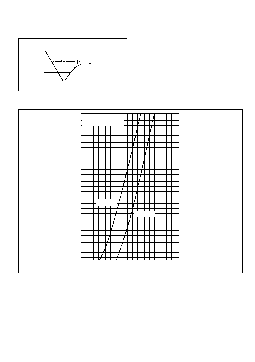
DEFINITION OF K FACTOR AND Q
RA1
0.5x I
RR
I
RR
dI
R
/dt
t
1
t
2
Q
RA1
= 0.5x I
RR
(t
1
+ t
2
)
k = t
1
/t
2
CURVES
500
750
1000
1250
1500
1750
2000
Instantaneous forward current I
F
- (A)
1.0
2.0
3.0
4.0
5.0
Instantaneous forward voltage V
F
- (V)
Measured under pulse
conditions
T
j
= 150∞C
T
j
= 25∞C
Fig.1 Maximum (limit) forward characteristics
TV18..F
4/8
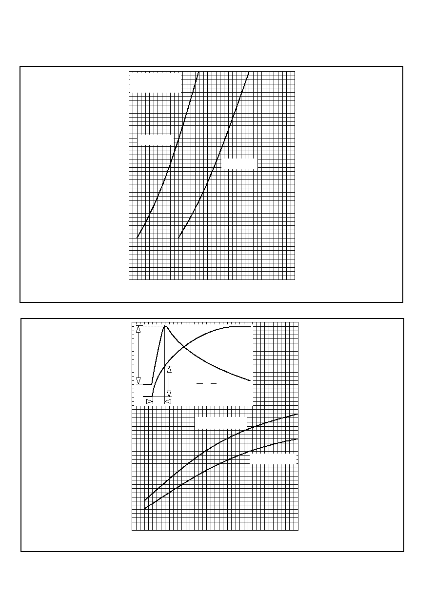
Fig.2 Maximum (limit) forward characteristics
0
100
200
300
400
500
Instantaneous forward current I
F
- (A)
1.0
1.5
2.0
2.5
3.0
Instantaneous forward voltage V
F
- (V)
Measured under
pulse conditions
T
j
= 150∞C
T
j
= 25∞C
0
50
100
150
200
250
Transient forward votage V
FP
- (V)
0
500
1000
1500
2000
Rate of rise of forward current dI
F
/dt - (A/
µ
s)
T
j
= 100∞C limit
T
j
= 25∞C limit
Current
waveform
Voltage
waveform
V
FR
y
x
di =
y
dt
x
Fig.3 Transient forward voltage vs rate of rise of forward current
TV18..F
5/8
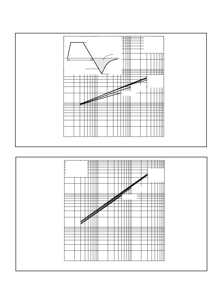
1
10
100
1000
Rate of rise of reverse current dI
R
/dt - (A/
µ
s)
100
10
1000
10000
Reverse recovered charge Q
S
- (
µ
C)
I
RR
QS
t
p
= 1ms
I
F
dI
R
/dt
Q
S
=
Conditions:
T
j
= 150∞C,
V
R
= 100V
50
µ
s
0
I
F
= 1000A
I
F
= 750A
I
F
= 500A
I
F
= 200A
I
F
= 100A
Fig.4 Recovered charge
1
10
100
1000
Rate of rise of reverse current dI
R
/dt - (A/
µ
s)
10
1
100
10000
Reverse recovery current I
RR
- (A)
Conditions:
T
j
= 150∞C,
V
R
= 100V
I
F
= 1000A
I
F
= 750A
I
F
= 500A
I
F
= 200A
I
F
= 100A
Fig.5 Typical reverse recovery current vs rate of rise of reverse current