 | –≠–ª–µ–∫—Ç—Ä–æ–Ω–Ω—ã–π –∫–æ–º–ø–æ–Ω–µ–Ω—Ç: LT1015CJ8 | –°–∫–∞—á–∞—Ç—å:  PDF PDF  ZIP ZIP |
1
LT1015
s
Response Time: 10ns
s
Setup Time for Latch: 2ns
s
Operates on Single 5V Supply
s
Dual Function in 8-Pin Package
s
No Input Slew Rate Requirement
s
Latch Function Included on Chip
s
True Differential Inputs
The LT
Æ
1015 is a dual high speed comparator intended for
line receiver and other general purpose fast comparator
functions. It has 10ns response time, true differential
inputs, TTL outputs and operates from a single 5V supply.
A unique output stage design virtually eliminates power
supply glitching during transitions. This greatly reduces
instability and crosstalk problems in multiple line applica-
tions. No minimum input slew rate is required as in
previous TTL output comparators.
The LT1015 has a true Latch pin for retaining output data.
Setup time is 2ns, allowing the comparators to capture
data much faster than the actual flowthrough response
time. 8-pin miniDIP and ceramic packages allow high
packing density.
High Speed
Dual Line Receiver
FEATURES
DESCRIPTIO
N
U
s
High Speed Differential Line Receiver
s
Pulse Height/Width Discriminator
s
Timing and Delay Generators
s
Analog to Digital Interface
APPLICATIO
N
S
U
, LTC and LT are registered trademarks of Linear Technology Corporation.
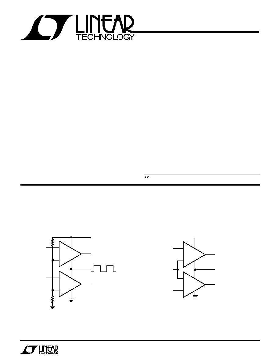
TYPICAL APPLICATIO
N
U
≠
+
≠
+
1/2
LT1015
1/2
LT1015
INPUT A
INPUT B
5V
CHANNEL A
CHANNEL B
DATA LATCHED
ON POSITIVE EDGE
CLOCK
1015 ∑ TA01
≠
+
≠
+
1/2
LT1015
1/2
LT1015
INPUT A
REFERENCE
INPUT
INPUT B
V
+
OUTPUT A
LATCH (BOTH SIDES)
DEVICE ACTIVE WITH
LATCH LOW. "OPEN"
GOES TO HIGH STATE
OUTPUT B
1015 ∑ BD
BLOCK DIAGRA
M
W
2-Channel 20MHz Clocked Line Receiver

2
LT1015
ORDER PART
NUMBER
Supply Voltage .......................................................... 7V
Differential Input Voltage ........................................... 5V
Input Voltage
Positive................................................ Supply + 0.5V
Negative .............................................................. ≠ 1V
Input Current (Forced) Positive ............................ 20mA
Latch Pin Voltage ........................................ Supply + 1V
Output Current (Continuous) ..............................
±
20mA
Operating Temperature Range
LT1015C .................................................. 0
∞
C to 70
∞
C
LT1015M ........................................ ≠ 55
∞
C to 125
∞
C*
Storage Temperature ............................ ≠ 65
∞
C to 150
∞
C
Lead Temperature (Soldering, 10 sec).................. 300
∞
C
*Air flow must be provided for T
A
> 100
∞
C
ABSOLUTE
M
AXI
M
U
M
RATINGS
W
W
W
U
PACKAGE/ORDER I
N
FOR
M
ATIO
N
W
U
U
Consult factory for Industrial grade parts.
V
+
= 4.6V to 5.4V, V
LATCH
= 0V, common mode input voltage = 2.5V, T
J
= 25
∞
C, unless otherwise noted.
ELECTRICAL CHARACTERISTICS
PARAMETER
CONDITIONS
MIN
TYP
MAX
UNITS
Input Offset Voltage (Note 1)
V
CM
= 1.25V to (V
+
≠ 1.5V)
q
1
20
mV
Input Bias Current
V
IN
= 0V (Note 2)
q
15
30
µ
A
Reference Input Current
V
IN
= 0V (Note 2)
q
30
60
µ
A
Voltage Gain (Note 3)
V
OUT
= 0.5V to 2.5V, Load = 1 TTL Gate
q
1000
2500
V/V
Common Mode Input Range (Note 5) Minimum Input
q
1.0
1.25
V
Maximum Input
q
V
+
≠ 1.5
V
+
≠ 1.0
V
Output High Voltage
I
OUT
= 4mA
q
2.5
V
Output Low Voltage
I
SINK
= 4mA
q
0.3
0.5
V
Supply Current
V
+
= 5V
q
55
70
mA
Latch Pin High Input Voltage
Device Latched
q
2
V
Latch Pin Low Input Voltage
Device Active
q
0.8
V
Latch Pin Current
q
1
mA
Propagation Delay
V
IN
20mV (Note 4)
0
∞
C
T
J
100
∞
C
q
7
10
14
ns
≠ 55
∞
C
T
J
150
∞
C
q
7
10
16
ns
Latch Setup Time
2
ns
LT1015CJ8
LT1015CN8
LT1015MJ8
1
2
3
4
8
7
6
5
TOP VIEW
INPUT A
REFERENCE
INPUT B
LATCH
V
+
OUTPUT A
GND
OUTPUT B
J8 PACKAGE
8-LEAD CERDIP
N8 PACKAGE
8-LEAD PDIP
T
JMAX
= 150
∞
C,
JA
= 100
∞
C/ W (J8)
T
JMAX
= 100
∞
C,
JA
= 130
∞
C/ W (N8)
The
q
denotes specifications which apply over the full operating
temperature range.
Note 1: Input offset voltage is the maximum required to drive the output to
a low state of 0.5V and high state of 2.5V.
Note 2: Input currents are measured by applying a large positive
differential input voltage. The resulting input current is divided by two to
obtain input current at
V
IN
= 0V.
Note 3: Voltage gain is guaranteed by design, but not tested.
Note 4: Propagation delay is sample tested in production with a large
overdrive. The limit is guard banded to account for the slight increase
(
500ps) at 20mV overdrive.
Note 5: Common mode input range is the voltage range over which the
differential input offset voltage is less than 20mV. If both inputs remain
inside this common mode range, propagation delay will be unaffected. It
will also be normal if the signal input is below the 1.25V lower limit when
the input transition begins. An increase in propagation delay of up to 10ns
may occur if the signal input is above the upper common mode limit when
the transition begins. Sine wave inputs may not be affected when the peak
exceeds the common mode range if the signal is inside the common mode
range for 10ns before threshold is reached.

3
LT1015
Information furnished by Linear Technology Corporation is believed to be accurate and reliable.
However, no responsibility is assumed for its use. Linear Technology Corporation makes no represen-
tation that the interconnection of its circuits as described herein will not infringe on existing patent rights.
TYPICAL PERFOR
M
A
N
CE CHARACTERISTICS
U
W
Latch Set-Up Time
OVERDIRVE (mV)
0
TIME (ns)
25
20
15
10
5
0
40
LT1015 ∑ TPC01
10
20
30
50
STEP SIZE = 100mV
T
J
= 25
∞
C
Propagation Delay vs Overdrive
JUNCTION TEMPERATURE (
∞
C)
≠50
TIME (ns)
6
4
2
0
≠2
≠4
≠6
25
75
LT1015 ∑ TPC03
≠25
0
50
100
125
JUNCTION TEMPERATURE (
∞
C)
≠50
TIME (ns)
30
25
20
15
10
5
0
25
75
LT1015 ∑ TPC02
≠25
0
50
100
125
FALLING OUTPUT t
PDHL
RISING OUTPUT t
PDHL
STEP SIZE = 100mV
OVERDRIVE = 5mV
OUTPUT LOAD CAPACITANCE = 10pF
V
S
= 5V
Propagation Delay vs Temperature
Common Mode Limits
Output Low Voltage (V
OL
)
Output High Voltage (V
OH
)
OUTPUT SINK CURRENT (mA)
0
VOLTAGE (V)
0.8
0.7
0.6
0.5
0.4
0.3
0.2
0.1
0
16
LT1015 ∑ TPC04
4
8
12 14
2
6
10
18 20
T
J
= ≠55
∞
C
T
J
= 25
∞
C
T
J
= 125
∞
C
V
S
= 5V, V
IN
= 30mV
OUTPUT SINK CURRENT (mA)
0
OUTPUT VOLTAGE (V)
5.0
4.5
4.0
3.5
3.0
2.5
2.0
1.5
1.0
16
LT1015 ∑ TPC05
4
8
12 14
2
6
10
18 20
T
J
= 125
∞
C
T
J
= 25
∞
C
T
J
= ≠55
∞
C
V
S
= 5V
JUNCTION TEMPERATURE (
∞
C)
≠50
INPUT VOLTAGE (V)
6
5
4
3
2
1
0
25
75
LT1015 ∑ TPC06
≠25
0
50
100
125
V
S
= 5V
V
S
= SINGLE 5V SUPPLY
LOWER LIMIT
UPPER LIMIT*
* UPPER LIMIT TRACKS 5V SUPPLY. 4.1V LIMIT
AT 25
∞
C WILL DROP TO 3.8V WHEN V
S
= 4.7V

4
LT1015
Linear Technology Corporation
1630 McCarthy Blvd., Milpitas, CA 95035-7417
(408) 432-1900
q
FAX
: (408) 434-0507
q
TELEX
: 499-3977
LT/GP 1195 1K REV A ∑ PRINTED IN USA
©
LINEAR TECHNOLOGY CORPORATION 1995
PART NUMBER
DESCRIPTION
COMMENTS
LT1016
Ultrafast Precision Comparator
10ms Propagation Delay, Complimentary TTL Outputs
LT1116
12ns, Single-Supply Ground Sensing Comparator
Inputs Can Exceed Positive Supply Up to 15V
LTC
Æ
1520
50Mbits/s Precision Quad Line Driver
18ns Propagation Delay Over Temperature Rail-to-Rail Inputs
PACKAGE DESCRIPTIO
N
U
Dimensions in inches (millimeters) unless otherwise noted.
N8 0695
0.005
(0.127)
MIN
0.100
±
0.010
(2.540
±
0.254)
0.065
(1.651)
TYP
0.045 ≠ 0.065
(1.143 ≠ 1.651)
0.130
±
0.005
(3.302
±
0.127)
0.015
(0.380)
MIN
0.018
±
0.003
(0.457
±
0.076)
0.125
(3.175)
MIN
1
2
3
4
8
7
6
5
0.255
±
0.015*
(6.477
±
0.381)
0.400*
(10.160)
MAX
0.009 ≠ 0.015
(0.229 ≠ 0.381)
0.300 ≠ 0.325
(7.620 ≠ 8.255)
0.325
+0.025
≠0.015
+0.635
≠0.381
8.255
(
)
*THESE DIMENSIONS DO NOT INCLUDE MOLD FLASH OR PROTRUSIONS.
MOLD FLASH OR PROTRUSIONS SHALL NOT EXCEED 0.010 INCH (0.254mm)
N8 Package
8-Lead PDIP (Narrow 0.300)
(LTC DWG # 05-08-1510)
RELATED PARTS
J8 Package
8-Lead CERDIP (Narrow 0.300, Hermetic)
(LTC DWG # 05-08-1110)
J8 0694
0.014 ≠ 0.026
(0.360 ≠ 0.660)
0.200
(5.080)
MAX
0.015 ≠ 0.060
(0.381 ≠ 1.524)
0.125
3.175
MIN
0.100
±
0.010
(2.540
±
0.254)
0.300 BSC
(0.762 BSC)
0.008 ≠ 0.018
(0.203 ≠ 0.457)
0
∞
≠ 15
∞
0.385
±
0.025
(9.779
±
0.635)
0.005
(0.127)
MIN
0.405
(10.287)
MAX
0.220 ≠ 0.310
(5.588 ≠ 7.874)
1
2
3
4
8
7
6
5
0.025
(0.635)
RAD TYP
0.045 ≠ 0.068
(1.143 ≠ 1.727)
FULL LEAD
OPTION
0.023 ≠ 0.045
(0.584 ≠ 1.143)
HALF LEAD
OPTION
CORNER LEADS OPTION
(4 PLCS)
0.045 ≠ 0.068
(1.143 ≠ 1.727)
NOTE: LEAD DIMENSIONS APPLY TO SOLDER DIP/PLATE OR TIN PLATE LEADS.