 | –≠–ª–µ–∫—Ç—Ä–æ–Ω–Ω—ã–π –∫–æ–º–ø–æ–Ω–µ–Ω—Ç: LTC1661I | –°–∫–∞—á–∞—Ç—å:  PDF PDF  ZIP ZIP |
1
LTC1661
Micropower Dual
10-Bit DAC in MSOP
The LTC
Æ
1661 integrates two accurate, serially addres-
sable, 10-bit digital-to-analog converters (DACs) in a
single tiny MS8 package. Each buffered DAC draws just
60
µ
A total supply current, yet is capable of supplying DC
output currents in excess of 5mA and reliably driving
capacitive loads up to 1000pF. Sleep mode further re-
duces total supply current to a negligible 1
µ
A.
Linear Technology's proprietary, inherently monotonic
voltage interpolation architecture provides excellent lin-
earity while allowing for an exceptionally small external
form factor. The double-buffered input logic provides
simultaneous update capability and can be used to write to
either DAC without interrupting Sleep mode.
Ultralow supply current, power-saving Sleep mode and
extremely compact size make the LTC1661 ideal for
battery-powered applications, while its straightforward
usability, high performance and wide supply range make
it an excellent choice as a general purpose converter.
For additional outputs and even greater board density,
please refer to the LTC1660 micropower octal DAC for
10-bit applications. For 8-bit applications, please consult
the LTC1665 micropower octal DAC.
s
Tiny: Two 10-Bit DACs in an 8-Lead MSOP--
Half the Board Space of an SO-8
s
Micropower: 60
µ
A per DAC
Sleep Mode: 1
µ
A for Extended Battery Life
s
Rail-to-Rail Voltage Outputs Drive 1000pF
s
Wide 2.7V to 5.5V Supply Range
s
Double Buffered for Independent or Simultaneous
DAC Updates
s
Reference Range Includes Supply for Ratiometric
0V-to-V
CC
Output
s
Reference Input Has Constant Impedance over All
Codes (260k
Typ)--Eliminates External Buffers
s
3-Wire Serial Interface with
Schmitt Trigger Inputs
s
Differential Nonlinearity:
±
0.75LSB Max
, LTC and LT are registered trademarks of Linear Technology Corporation.
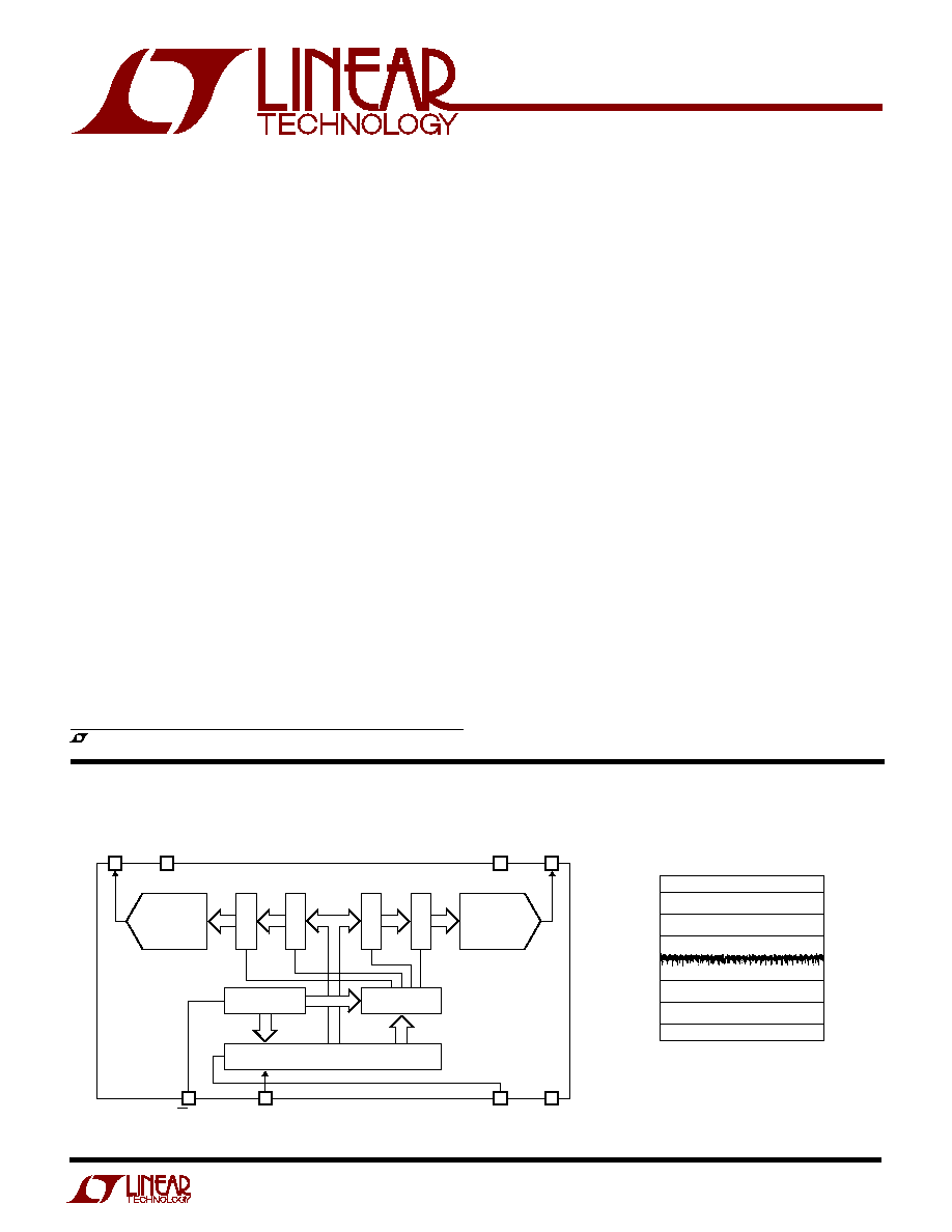
CS/LD
1661 BD
1
4
10-BIT
DAC A
10-BIT
DAC B
ADDRESS
DECODER
CONTROL
LOGIC
SHIFT REGISTER
SCK
2
D
IN
REF
3
V
OUT
A
8
5
GND
7
V
CC
V
OUT
B
6
LATCH
LATCH
LATCH
LATCH
Differential Nonlinearity (DNL)
s
Mobile Communications
s
Digitally Controlled Amplifiers and Attenuators
s
Portable Battery-Powered Instruments
s
Automatic Calibration for Manufacturing
s
Remote Industrial Devices
APPLICATIO S
U
FEATURES
DESCRIPTIO
U
BLOCK DIAGRA
W
CODE
0
256
512
768
1023
LSB
1661 G02
0.75
≠0.75
0.60
0.40
0.20
0
≠0.20
≠0.40
≠0.60

2
LTC1661
A
U
G
W
A
W
U
W
A
R
BSOLUTE
XI
TI
S
(Note 1)
V
CC
to GND .............................................. ≠ 0.3V to 7.5V
Logic Inputs to GND ................................ ≠ 0.3V to 7.5V
V
OUT A
, V
OUT B
, REF to GND ............ ≠ 0.3V to V
CC
+ 0.3V
Maximum Junction Temperature ......................... 125
∞
C
Storage Temperature Range ................ ≠ 65
∞
C to 150
∞
C
Operating Temperature Range
LTC1661C ............................................. 0
∞
C to 70
∞
C
LTC1661I ........................................... ≠ 40
∞
C to 85
∞
C
Lead Temperature (Soldering, 10 sec)................ 300
∞
C
ELECTRICAL C
C
HARA TERISTICS
SYMBOL
PARAMETER
CONDITIONS
MIN
TYP
MAX
UNITS
Accuracy
Resolution
q
10
Bits
Monotonicity
1V
V
REF
V
CC
≠ 0.1V (Note 2)
q
10
Bits
DNL
Differential Nonlinearity
1V
V
REF
V
CC
≠ 0.1V (Note 2)
q
±
0.1
±
0.75
LSB
INL
Integral Nonlinearity
1V
V
REF
V
CC
≠ 0.1V (Note 2)
q
±
0.4
±
2
LSB
V
OS
Offset Error
Measured at Code 20
q
±
5
±
30
mV
V
OS
Temperature Coefficient
±
15
µ
V/
∞
C
FSE
Full-Scale Error
V
CC
= 5V, V
REF
= 4.096V
q
±
1
±
12
LSB
Full-Scale Error Temperature Coefficient
±
30
µ
V/
∞
C
PSR
Power Supply Rejection
V
REF
= 2.5V
0.18
LSB/V
Reference Input
Input Voltage Range
q
0
V
CC
V
Resistance
Active Mode
q
140
260
k
Capacitance
q
15
pF
I
REF
Reference Current
Sleep Mode
q
0.001
1
µ
A
Power Supply
V
CC
Positive Supply Voltage
For Specified Performance
q
2.7
5.5
V
I
CC
Supply Current
V
CC
= 5V (Note 3)
q
120
195
µ
A
V
CC
= 3V (Note 3)
q
95
154
µ
A
Sleep Mode (Note 3)
q
1
3
µ
A
W
U
U
PACKAGE/ORDER I FOR ATIO
ORDER PART
NUMBER
MS8 PART MARKING
ORDER PART
NUMBER
T
JMAX
= 125
∞
C,
JA
= 150
∞
C/W
1
2
3
4
CS/LD
SCK
D
IN
REF
8
7
6
5
V
OUT A
GND
V
CC
V
OUT B
TOP VIEW
MS8 PACKAGE
8-LEAD PLASTIC MSOP
1
2
3
4
8
7
6
5
TOP VIEW
CS/LD
SCK
D
IN
REF
V
OUT A
GND
V
CC
V
OUT B
N8 PACKAGE
8-LEAD PLASTIC DIP
LTC1661CN8
LTC1661IN8
LTC1661CMS8
LTC1661IMS8
Consult factory for Military grade parts.
T
JMAX
= 125
∞
C,
JA
= 100
∞
C/W
LTDV
LTDW
The
q
denotes the specifications which apply over the full operating
temperature range, otherwise specifications are at T
A
= 25
∞
C. V
CC
= 2.7V to 5.5V, V
REF
V
CC
, V
OUT
Unloaded unless otherwise noted.

3
LTC1661
ELECTRICAL C
C
HARA TERISTICS
TI I G CHARACTERISTICS
U
W
SYMBOL
PARAMETER
CONDITIONS
MIN
TYP
MAX
UNITS
V
CC
= 4.5V to 5.5V
t
1
D
IN
Valid to SCK Setup
q
40
15
ns
t
2
D
IN
Valid to SCK Hold
q
0
≠ 10
ns
t
3
SCK High Time
(Note 6)
q
30
14
ns
t
4
SCK Low Time
(Note 6)
q
30
14
ns
t
5
CS/LD Pulse Width
(Note 6)
q
80
27
ns
t
6
LSB SCK High to CS/LD High
(Note 6)
q
30
2
ns
t
7
CS/LD Low to SCK High
(Note 6)
q
20
≠ 21
ns
t
9
SCK Low to CS/LD Low
(Note 6)
q
0
≠ 5
ns
t
11
CS/LD High to SCK Positive Edge
(Note 6)
q
20
0
ns
SCK Frequency
Square Wave (Note 6)
q
16.7
MHz
V
CC
= 2.7V to 5.5V
t
1
D
IN
Valid to SCK Setup
(Note 6)
q
60
20
ns
t
2
D
IN
Valid to SCK Hold
(Note 6)
q
0
≠ 10
ns
t
3
SCK High Time
(Note 6)
q
50
15
ns
t
4
SCK Low Time
(Note 6)
q
50
15
ns
t
5
CS/LD Pulse Width
(Note 6)
q
100
30
ns
t
6
LSB SCK High to CS/LD High
(Note 6)
q
50
3
ns
t
7
CS/LD Low to SCK High
(Note 6)
q
30
≠ 14
ns
t
9
SCK Low to CS/LD Low
(Note 6)
q
0
≠ 5
ns
t
11
CS/LD High to SCK Positive Edge
(Note 6)
q
30
0
ns
SCK Frequency
Square Wave (Note 6)
q
10
MHz
SYMBOL
PARAMETER
CONDITIONS
MIN
TYP
MAX
UNITS
DC Performance
Short-Circuit Current Low
V
OUT
= 0V, V
CC
= V
REF
= 5V, Code = 1023
q
10
25
100
mA
Short-Circuit Current High
V
OUT
= V
CC
= V
REF
= 5V, Code = 0
q
7
19
120
mA
AC Performance
Voltage Output Slew Rate
Rising (Notes 4, 5)
0.60
V/
µ
s
Falling (Notes 4, 5)
0.25
V/
µ
s
Voltage Output Settling Time
To
±
0.5LSB (Notes 4, 5)
30
µ
s
Capacitive Load Driving
1000
pF
Digital I/O
V
IH
Digital Input High Voltage
V
CC
= 2.7V to 5.5V
q
2.4
V
V
CC
= 2.7V to 3.6V
q
2.0
V
V
IL
Digital Input Low Voltage
V
CC
= 4.5V to 5.5V
q
0.8
V
V
CC
= 2.7V to 5.5V
q
0.6
V
I
LK
Digital Input Leakage
V
IN
= GND to V
CC
q
±
10
µ
A
C
IN
Digital Input Capacitance
(Note 6)
q
10
pF
The
q
denotes the specifications which apply over the full operating
temperature range, otherwise specifications are at T
A
= 25
∞
C. V
CC
= 2.7V to 5.5V, V
REF
V
CC
, V
OUT
Unloaded unless otherwise noted.
The
q
denotes the specifications which apply over the full operating temperature
range, otherwise specifications are at T
A
= 25
∞
C.
Note 1: Absolute maximum ratings are those values beyond which the life
of a device may be impaired.
Note 2: Nonlinearity and monotonicity are defined from code 20 to code
1023 (full scale). See Applications Information.
4
LTC1661
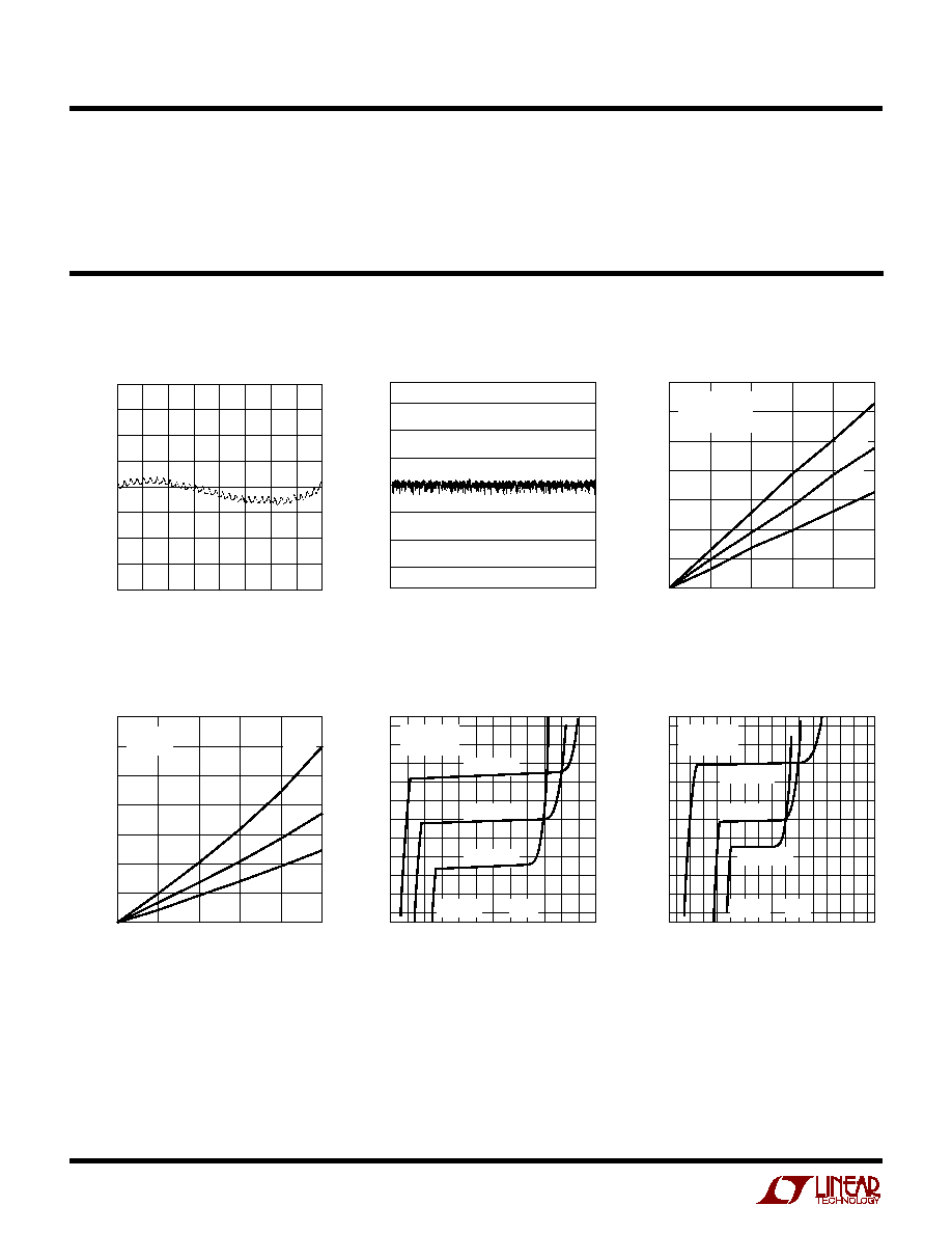
TYPICAL PERFOR A CE CHARACTERISTICS
U
W
Integral Nonlinearity (INL)
Differential Nonlinearity (DNL)
CODE
0
256
512
768
1023
LSB
1661 G01
2.0
1.5
1.0
0.5
0
≠0.5
≠1.0
≠1.5
≠2.0
CODE
0
256
512
768
1023
LSB
1661 G02
0.75
≠0.75
0.60
0.40
0.20
0
≠0.20
≠0.40
≠0.60
0
2
4
6
8
10
V
CC
≠ V
OUT
(mV)
1661 G03
1400
1200
1000
800
600
400
200
0
≠55
∞
C
25
∞
C
125
∞
C
V
REF
= 4.096V
V
OUT
< 1LSB
CODE = 1023
|
I
OUT
|
(mA) (Sourcing)
|
I
OUT
|
(mA) (Sinking)
0
2
4
6
8
10
V
OUT
(mV)
1661 G04
1400
1200
1000
800
600
400
200
0
≠55
∞
C
25
∞
C
125
∞
C
V
CC
= 5V
CODE = 0
I
OUT
(mA)
≠30
≠20
≠10
0
10
20
30
V
OUT
(V)
1661 G05
3
2.9
2.8
2.7
2.6
2.5
2.4
2.3
2.2
2.1
2
V
CC
= 4.5V
V
CC
= 5V
V
CC
= 5.5V
V
REF
= V
CC
CODE = 512
SINK
SOURCE
I
OUT
(mA)
≠15
≠4
≠8
≠12
0
4
8
12 15
V
OUT
(V)
1661 G06
2
1.9
1.8
1.7
1.6
1.5
1.4
1.3
1.2
1.1
1
V
CC
= 2.7V
V
CC
= 3V
V
CC
= 3.6V
V
REF
= V
CC
CODE = 512
SINK
SOURCE
Midscale Output Voltage vs
Load Current
Midscale Output Voltage vs
Load Current
Minimum Supply Headroom vs
Load Current (Output Sourcing)
Minimum V
OUT
vs
Load Current (Output Sinking)
Note 3: Digital inputs at 0V or V
CC
.
Note 4: Load is 10k
in parallel with 100pF.
TI I G CHARACTERISTICS
U
W
Note 5: V
CC
= V
REF
= 5V. DAC switched between 0.1V
FS
and 0.9V
FS
,
i.e., codes k = 102 and k = 922.
Note 6: Guaranteed by design and not subject to test.
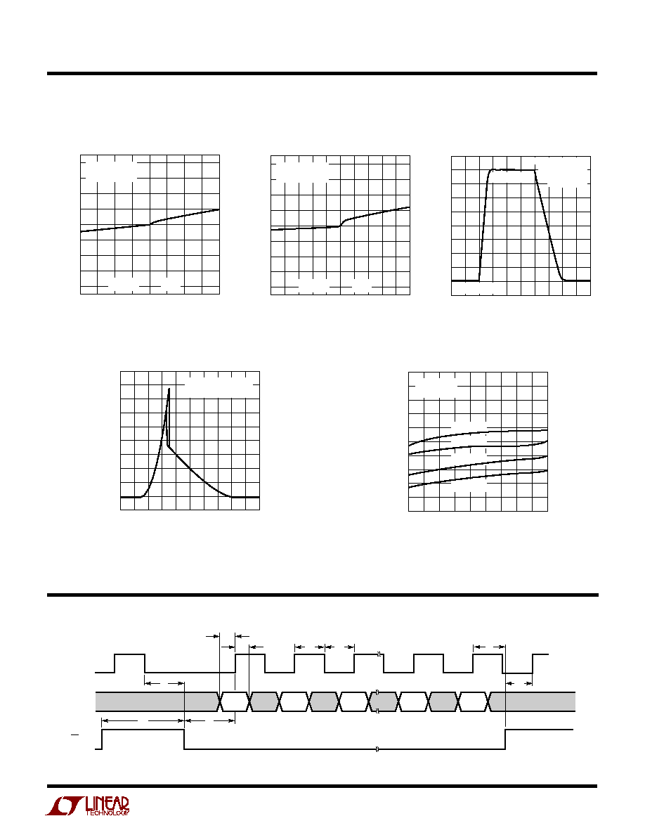
5
LTC1661
TYPICAL PERFOR A CE CHARACTERISTICS
U
W
I
OUT
(mA)
≠2
≠1
0
1
2
V
OUT
(LSB)
2
1.5
1
0.5
0
≠0.5
≠1
≠1.5
≠2
1661 G07
V
CC
= V
REF
= 5V
CODE = 512
SINK
SOURCE
I
OUT
(
µ
A)
≠500
0
500
V
OUT
(LSB)
2
1.5
1
0.5
0
≠0.5
≠1
≠1.5
≠2
1661 G08
SINK
SOURCE
V
CC
= V
REF
= 3V
CODE = 512
Load Regulation vs
Output Current
Load Regulation vs
Output Current
TIME (
µ
s)
0
20
40
60
80
100
V
OUT
(V)
1661 G09
5
4
3
2
1
0
V
CC
= V
REF
= 5V
10% TO
90% STEP
CODE = 102
CODE = 922
LOGIC INPUT VOLTAGE (V)
0
1
2
3
4
5
SUPPLY CURRENT (mA)
1661 G10
1.0
0.8
0.6
0.4
0.2
0
ALL DIGITAL INPUTS
SHORTED TOGETHER
TEMPERATURE (
∞
C)
≠55 ≠35 ≠15
5
25
45
65
85 105 125
SUPPLY CURRENT (
µ
A)
1661 G11
150
140
130
120
110
100
90
80
70
60
50
V
CC
= 5.5V
V
REF
= V
CC
CODE = 1023
V
CC
= 4.5V
V
CC
= 3.6V
V
CC
= 2.7V
Large-Signal Step Response
Supply Current vs
Logic Input Voltage
Supply Current vs Temperature
TI I G DIAGRA
U
W
W
D
IN
CS/LD
SCK
A3
A2
1661 TD
A1
X1
X0
t
2
t
9
t
11
t
5
t
7
t
6
t
1
t
3
t
4

6
LTC1661
PI
N
FU
N
CTIO
N
S
U
U
U
CS/LD (Pin 1): Serial Interface Chip Select/Load Input.
When CS/LD is low, SCK is enabled for shifting data on D
IN
into the register. When CS/LD is pulled high, SCK is
disabled and the operation(s) specified in the Control
code, A3-A0, is (are) performed. CMOS and TTL compat-
ible.
SCK (Pin 2): Serial Interface Clock Input. CMOS and TTL
compatible.
D
IN
(Pin 3): Serial Interface Data Input. Input word data on
the D
IN
pin is shifted into the 16-bit register on the rising
edge of SCK. CMOS and TTL compatible.
REF (Pin 4): Reference Voltage Input. 0V
V
REF
V
CC
.
V
OUT A
, V
OUT B
(Pins 8,5): DAC Analog Voltage Outputs.
The output range is
0
1023
1024
V
V
V
OUTA
OUTB
REF
,
V
CC
(Pin 6): Supply Voltage Input. 2.7V
V
CC
5.5V.
GND (Pin 7): System Ground.
DEFI
N
ITIO
N
S
U
U
INL = [V
OUT
≠ V
OS
≠ (V
FS
≠ V
OS
)(code/1023)]/LSB
Where V
OUT
is the output voltage of the DAC measured at
the given input code.
Least Significant Bit (LSB): The ideal voltage difference
between two successive codes.
LSB = V
REF
/1024
Resolution (n): Defines the number of DAC output states
(2
n
) that divide the full-scale range. Resolution does not
imply linearity.
Voltage Offset Error (V
OS
): Nominally, the voltage at the
output when the DAC is loaded with all zeros. A single
supply DAC can have a true negative offset, but the output
cannot go below zero (see Applications Information).
For this reason, single supply DAC offset is measured at
the lowest code that guarantees the output will be greater
than zero.
Differential Nonlinearity (DNL): The difference between
the measured change and the ideal 1LSB change for any
two adjacent codes. The DNL error between any two codes
is calculated as follows:
DNL = (
V
OUT
≠ LSB)/LSB
Where
V
OUT
is the measured voltage difference between
two adjacent codes.
Full-Scale Error (FSE): The deviation of the actual full-
scale voltage from ideal. FSE includes the effects of offset
and gain errors (see Applications Information).
Integral Nonlinearity (INL): The deviation from a straight
line passing through the endpoints of the DAC transfer
curve (Endpoint INL). Because the output cannot go below
zero, the linearity is measured between full scale and the
lowest code which guarantees the output will be greater
than zero. The INL error at a given input code is calculated
as follows:
7
LTC1661
OPERATIO
U
Transfer Function
The transfer function for the LTC1661 is:
V
k
V
OUT IDEAL
REF
(
)
=
1024
where k is the decimal equivalent of the binary DAC input
code D9-D0 and V
REF
is the voltage at REF (Pin 6).
Power-On Reset
The LTC1661 positively clears the outputs to zero scale
when power is first applied, making system initialization
consistent and repeatable.
Power Supply Sequencing
The voltage at REF (Pin 4) must not ever exceed the voltage
at V
CC
(Pin 6) by more than 0.3V. Particular care should be
taken in the power supply turn-on and turn-off sequences
to assure that this limit is observed. See Absolute Maxi-
mum Ratings.
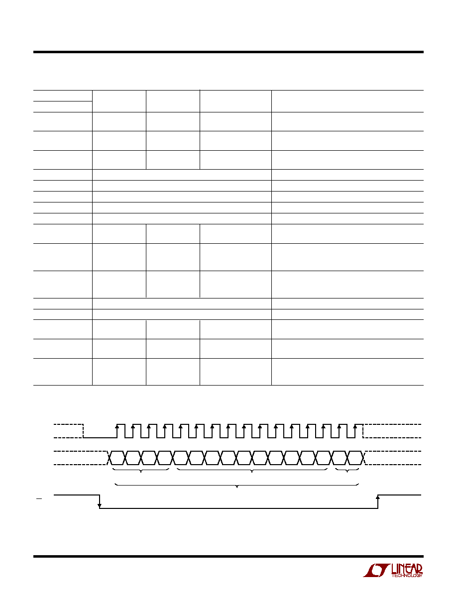
Serial Interface
See Table 1. The 16-bit Input word consists of the 4-bit
Control code, the 10-bit Input code and two don't-care bits.
Table 1. LTC1661 Input Word
By selecting the appropriate 4-bit Control code (see Table 2)
it is possible to perform single operations, such as loading
one DAC or changing Power-Down status (Sleep/Wake).
In addition, some Control codes perform two or more
operations at the same time. For example, one such code
loads DAC A, updates both outputs and Wakes the part up.
The DACs can be loaded separately or together, but the
outputs are always updated together.
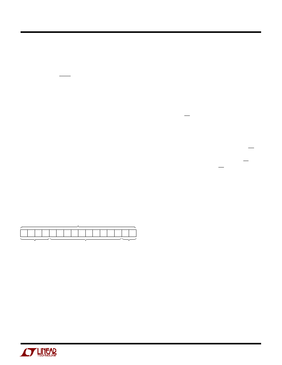
Register Loading Sequence
See Figure 1. With CS/LD held low, data on the D
IN
input
is shifted into the 16-bit Shift Register on the positive edge
of SCK. The 4-bit Control code, A3-A0, is loaded first, then
the 10-bit Input code, D9-D0, ordered MSB-to-LSB in each
case. Two don't-care bits, X1 and X0, are loaded last.
When the full 16-bit Input word has been shifted in, CS/LD
is pulled high, causing the system to respond according to
Table 2. The clock is disabled internally when CS/LD is
high. Note: SCK must be low when CS/LD is pulled low.
Sleep Mode
DAC control code 1110
b
is reserved for the special Sleep
instruction (see Table 2). In this mode, the digital parts of
the circuit stay active while the analog sections are dis-
abled; static power consumption is greatly reduced. The
reference input and analog outputs are set in a high
impedance state and all DAC settings are retained in
memory so that when Sleep mode is exited, the outputs of
DACs not updated by the Wake command are restored to
their last active state.
Sleep mode is initiated by performing a load sequence
using control code 1110
b
(the DAC input code D9-D0 is
ignored).
To save instruction cycles, the DACs may be prepared with
new input codes during Sleep (control codes 0001
b
and
0010
b
); then, a single command (1000
b
) can be used both
to wake the part and to update the output values.
A3 A2 A1
Control Code
A0 D9 D8 D7 D6 D5 D4 D3 D2 D1
X1 X0
D0
Input Code
Input Word
Don't
Care
After the Input word is loaded into the register (see Figure 1),
it is internally converted from serial to parallel format. The
parallel 10-bit-wide Input code data path is then buffered
by two latch registers.
The first of these, the Input Register, is used for loading new
input codes. The second buffer, the DAC Register, is used
for updating the DAC outputs. Each DAC has its own 10-bit
Input Register and 10-bit DAC Register.
8
LTC1661
OPERATIO
U
D
IN
SCK
CS/LD
A3
A2
INPUT CODE
DON'T CARE
A1
A0
D9
D8
D7
D6
D5
D4
D3
D2
D1
D0
X1
X0
1661 F01
16
15
14
13
12
11
10
9
8
7
6
5
4
3
2
1
(SCK ENABLED)
(LTC1661
RESPONDS)
CONTROL CODE
INPUT WORD W
0
Figure 1. Register Loading Sequence
Table 2. DAC Control Functions
CONTROL
INPUT REGISTER
DAC REGISTER
POWER-DOWN STATUS
A3
A2
A1
A0
STATUS
STATUS
(SLEEP/WAKE)
COMMENTS
0
0
0
0
No Change
No Update
No Change
No Operation. Power-Down Status Unchanged
(Part Stays In Wake or Sleep Mode)
0
0
0
1
Load DAC A
No Update
No Change
Load Input Register A with Data. DAC Outputs
Unchanged. Power-Down Status Unchanged
0
0
1
0
Load DAC B
No Update
No Change
Load Input Register B with Data. DAC Outputs
Unchanged. Power-Down Status Unchanged
0
0
1
1
Reserved
0
1
0
0
Reserved
0
1
0
1
Reserved
0
1
1
0
Reserved
0
1
1
1
Reserved
1
0
0
0
No Change
Update Outputs
Wake
Load Both DAC Regs with Existing Contents of Input
Regs. Outputs Update. Part Wakes Up
1
0
0
1
Load DAC A
Update Outputs
Wake
Load Input Reg A. Load DAC Regs with New Contents
of Input Reg A and Existing Contents of Reg B. Outputs
Update. Part Wakes Up
1
0
1
0
Load DAC B
Update Outputs
Wake
Load Input Reg B. Load DAC Regs with Existing Contents
of Input Reg A and New Contents of Reg B. Outputs
Update. Part Wakes Up
1
0
1
1
Reserved
1
1
0
0
Reserved
1
1
0
1
No Change
No Update
Wake
Part Wakes Up. Input and DAC Regs Unchanged. DAC
Outputs Reflect Existing Contents of DAC Regs
1
1
1
0
No Change
No Update
Sleep
Part Goes to Sleep. Input and DAC Regs Unchanged. DAC
Outputs Set to High Impedance State
1
1
1
1
Load DACs A, B
Update Outputs
Wake
Load Both Input Regs. Load Both DAC Regs with New
with Same
Contents of Input Regs. Outputs Update. Part Wakes Up
10-Bit Code

9
LTC1661
Voltage Outputs
Each of the rail-to-rail output amplifiers contained in the
LTC1661 can typically source or sink up to 5mA
(V
CC
= 5V). The outputs swing to within a few millivolts
of either supply when unloaded and have an equivalent
output resistance of 85
(typical) when driving a load to
the rails. The output amplifiers are stable driving capaci-
tive loads up to 1000pF.
A small resistor placed in series with the output can be
used to achieve stability for any load capacitance. A 1
µ
F
load can be successfully driven by inserting a 20
resistor
in series with the V
OUT
pin. A 2.2
µ
F load needs only a 10
resistor, and a 10
µ
F electrolytic capacitor can be used
without any resistor (the equivalent series resistance of
the capacitor itself provides the required small resis-
tance). In any of these cases, larger values of resistance,
capacitance or both may be substituted for the values
given.
OPERATIO
U
Rail-to-Rail Output Considerations
In any rail-to-rail DAC, the output swing is limited to
voltages within the supply range.
If the DAC offset is negative, the output for the lowest
codes limits at 0V as shown in Figure 2b.
Similarly, limiting can occur near full scale when the REF
pin is tied to V
CC
. If V
REF
= V
CC
and the DAC full-scale error
(FSE) is positive, the output for the highest codes limits at
V
CC
as shown in Figure 2c. No full-scale limiting can occur
if V
REF
is less than V
CC
≠ FSE.
Offset and linearity are defined and tested over the region
of the DAC transfer function where no output limiting can
occur.
Figure 2. Effects of Rail-to-Rail Operation On a DAC Transfer Curve. (a) Overall Transfer Function (b) Effect of Negative
Offset for Codes Near Zero Scale (c) Effect of Positive Full-Scale Error for Input Codes Near Full Scale When V
REF
= V
CC
1661 F02
INPUT CODE
(b)
OUTPUT
VOLTAGE
NEGATIVE
OFFSET
0V
512
0
1023
INPUT CODE
OUTPUT
VOLTAGE
(a)
V
REF
= V
CC
V
REF
= V
CC
(c)
INPUT CODE
OUTPUT
VOLTAGE
POSITIVE
FSE

10
LTC1661
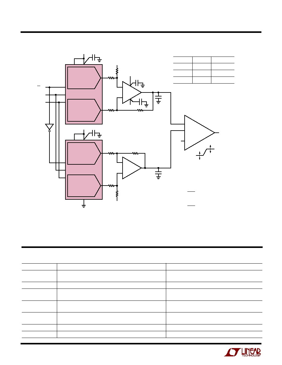
Figure 3. Pin Driver V
H
and V
L
Adjustment in ATE Applications
2
0.1
µ
F
V
IN
4.3V
LTC1258-4.1
1
4.096V
4
REF
D
IN
SCK
CS/LD
V
OUTA
GND
V
CC
LTC1661
V
OUTB
0V TO 4.096V
(4mV/BIT)
T
0V TO 4.096V
(4mV/BIT)
1661 F04
4
3
2
1
8
5
7
6
0.1
µ
F
≠
+
U3A
LT1368
PIN
DRIVER
(1 0F N)
V
H
V
L
V
OUT
1661 F03
LOGIC
DRIVE
4
≠5V
10V
5V
V
H
= 7.5V
(FROM MAIN
INPUT DAC)
V
L
= ≠2.5V
(FROM MAIN
INPUT DAC)
V
A1
= 2.5V
V
H
= V
H
+
V
H
V
L
= V
L
+
V
L
V
B1
R4
5k
0.1
µ
F
8
3
1
CS/LD
D
IN
SCK
4 6
3
2
1
8
5
2
0.1
µ
F
R3
50k
LTC1661
U1
DAC A
DAC B
R2
50k
R1
5k
0.1
µ
F
+
≠
U3B
LT1368
5V
V
B2
V
A2
= 2.5V
6
1
4 6
3
2
7
5
8
5
0.1
µ
F
R7
50k
LTC1661
U2
DAC B
DAC A
R5
50k
R6
5k
7
R8
5k
0.1
µ
F
0.1
µ
F
FOR EACH U1 AND U2
CODE A CODE B
V
H
,
V
L
512
1023
≠250mV
512
512
0
512
0
250mV
≠2.5V
±
250mV
7.5V
±
250mV
V
A2
= 2.5V
V
A1
=
V
H
+
(V
A1
≠ V
B1
)
V
H
=
R1
R2
V
L
+
(V
A2
≠ V
B2
)
V
L
=
FOR VALUES SHOWN,
V
H
,
V
L
ADJUSTMENT RANGE =
±
250mV
V
H
,
V
L
STEP SIZE = 500
µ
V
R1
R2
Figure 4. Using the LTC1258 and the LTC1661 In a Single Li-Ion Battery Application
TYPICAL APPLICATIO S
U
11
LTC1661
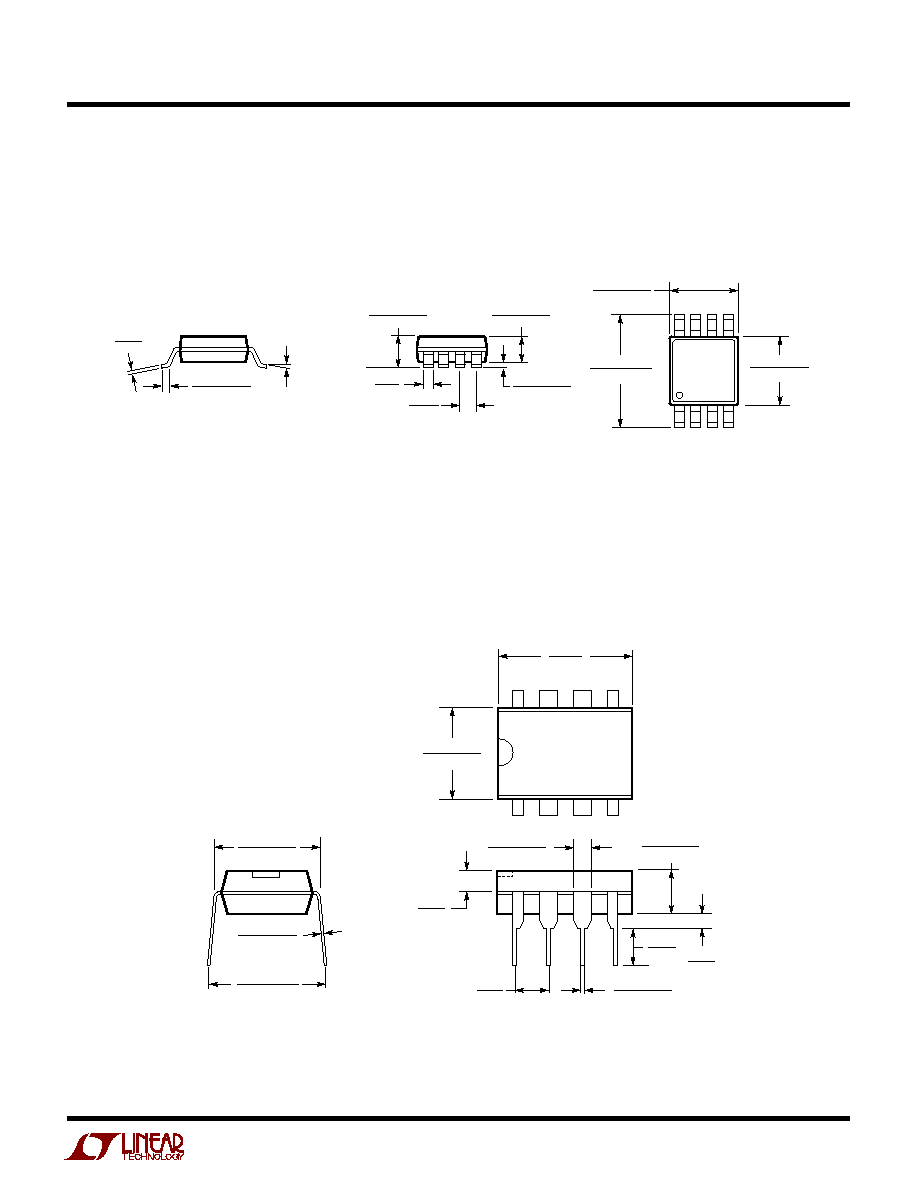
PACKAGE DESCRIPTIO
N
U
Dimensions in inches (millimeters) unless otherwise noted.
MS8 Package
8-Lead Plastic MSOP
(LTC DWG # 05-08-1660)
N8 Package
8-Lead PDIP (Narrow 0.300)
(LTC DWG # 05-08-1510)
MSOP (MS8) 1098
* DIMENSION DOES NOT INCLUDE MOLD FLASH, PROTRUSIONS OR GATE BURRS. MOLD FLASH,
PROTRUSIONS OR GATE BURRS SHALL NOT EXCEED 0.006" (0.152mm) PER SIDE
** DIMENSION DOES NOT INCLUDE INTERLEAD FLASH OR PROTRUSIONS.
INTERLEAD FLASH OR PROTRUSIONS SHALL NOT EXCEED 0.006" (0.152mm) PER SIDE
0.021
±
0.006
(0.53
±
0.015)
0
∞
≠ 6
∞
TYP
SEATING
PLANE
0.007
(0.18)
0.040
±
0.006
(1.02
±
0.15)
0.012
(0.30)
REF
0.006
±
0.004
(0.15
±
0.102)
0.034
±
0.004
(0.86
±
0.102)
0.0256
(0.65)
BSC
1
2
3
4
0.193
±
0.006
(4.90
±
0.15)
8
7 6
5
0.118
±
0.004*
(3.00
±
0.102)
0.118
±
0.004**
(3.00
±
0.102)
N8 1098
0.100
(2.54)
BSC
0.065
(1.651)
TYP
0.045 ≠ 0.065
(1.143 ≠ 1.651)
0.130
±
0.005
(3.302
±
0.127)
0.020
(0.508)
MIN
0.018
±
0.003
(0.457
±
0.076)
0.125
(3.175)
MIN
1
2
3
4
8
7
6
5
0.255
±
0.015*
(6.477
±
0.381)
0.400*
(10.160)
MAX
0.009 ≠ 0.015
(0.229 ≠ 0.381)
0.300 ≠ 0.325
(7.620 ≠ 8.255)
0.325
+0.035
≠0.015
+0.889
≠0.381
8.255
(
)
*THESE DIMENSIONS DO NOT INCLUDE MOLD FLASH OR PROTRUSIONS.
MOLD FLASH OR PROTRUSIONS SHALL NOT EXCEED 0.010 INCH (0.254mm)
Information furnished by Linear Technology Corporation is believed to be accurate and reliable.
However, no responsibility is assumed for its use. Linear Technology Corporation makes no represen-
tation that the interconnection of its circuits as described herein will not infringe on existing patent rights.
12
LTC1661
©
LINEAR TECHNOLOGY CORPORATION 1999
1661f LT/TP 0100 4K ∑ PRINTED IN THE USA
PART NUMBER
DESCRIPTION
COMMENTS
LTC1446/LTC1446L
Dual 12-Bit V
OUT
DACs in SO-8 Package with Internal Reference
LTC1446: V
CC
= 4.5V to 5.5V, V
OUT
= 0V to 4.095V
LTC1446L: V
CC
= 2.7V to 5.5V, V
OUT
= 0V to 2.5V
LTC1448
Dual 12-Bit V
OUT
DAC in SO-8 Package
V
CC
= 2.7V to 5.5V, External Reference Can Be Tied to V
CC
LTC1454/LTC1454L
Dual 12-Bit V
OUT
DACs in SO-16 Package with Added Functionality
LTC1454: V
CC
= 4.5V to 5.5V, V
OUT
= 0V to 4.095V
LTC1454L: V
CC
= 2.7V to 5.5V, V
OUT
= 0V to 2.5V
LTC1458/LTC1458L
Quad 12-Bit Rail-to-Rail Output DACs with Added Functionality
LTC1458: V
CC
= 4.5V to 5.5V, V
OUT
= 0V to 4.095V
LTC1458L: V
CC
= 2.7V to 5.5V, V
OUT
= 0V to 2.5V
LTC1659
Single Rail-to-Rail 12-Bit V
OUT
DAC in 8-Lead MSOP Package
Low Power Multiplying V
OUT
DAC. Output Swings from
V
CC
: 2.7V to 5.5V
GND to REF. REF Input Can Be Tied to V
CC
LTC1663
Single 10-Bit V
OUT
DAC in SOT-23 Package
V
CC
= 2.7V to 5.5V, Internal Reference, 60
µ
A
LTC1665/LTC1660
Octal 8/10-Bit V
OUT
DAC in 16-Pin Narrow SSOP
V
CC
= 2.7V to 5.5V, Micropower, Rail-to-Rail Output
RELATED PARTS
Linear Technology Corporation
1630 McCarthy Blvd., Milpitas, CA 95035-7417
(408) 432-1900
q
FAX: (408) 434-0507
q
www.linear-tech.com
TYPICAL APPLICATIO
U
Pin Driver V
H
and V
L
Adjustment in ATE Applications
≠
+
U3A
LT1368
PIN
DRIVER
(1 0F N)
V
H
V
L
V
OUT
1661 F03
LOGIC
DRIVE
4
≠5V
10V
5V
V
H
= 7.5V
(FROM MAIN
INPUT DAC)
V
L
= ≠2.5V
(FROM MAIN
INPUT DAC)
V
A1
= 2.5V
V
H
= V
H
+
V
H
V
L
= V
L
+
V
L
V
B1
R4
5k
0.1
µ
F
8
3
1
CS/LD
D
IN
SCK
4 6
3
2
1
8
5
2
0.1
µ
F
R3
50k
LTC1661
U1
DAC A
DAC B
R2
50k
R1
5k
0.1
µ
F
+
≠
U3B
LT1368
5V
V
B2
V
A2
= 2.5V
6
1
4 6
3
2
7
5
8
5
0.1
µ
F
R7
50k
LTC1661
U2
DAC B
DAC A
R5
50k
R6
5k
7
R8
5k
0.1
µ
F
0.1
µ
F
FOR EACH U1 AND U2
CODE A CODE B
V
H
,
V
L
512
1023
≠250mV
512
512
0
512
0
250mV
≠2.5V
±
250mV
7.5V
±
250mV
V
A2
= 2.5V
V
A1
=
V
H
+
(V
A1
≠ V
B1
)
V
H
=
R1
R2
V
L
+
(V
A2
≠ V
B2
)
V
L
=
FOR VALUES SHOWN,
V
H
,
V
L
ADJUSTMENT RANGE =
±
250mV
V
H
,
V
L
STEP SIZE = 500
µ
V
R1
R2