 | –≠–ª–µ–∫—Ç—Ä–æ–Ω–Ω—ã–π –∫–æ–º–ø–æ–Ω–µ–Ω—Ç: LTC1731 | –°–∫–∞—á–∞—Ç—å:  PDF PDF  ZIP ZIP |
1
LTC4054L-4.2
4054l42f
150mA Standalone Linear
Li-Ion Battery Charger in ThinSOT
, LTC and LT are registered trademarks of Linear Technology Corporation.
s
Programmable Charge Current Range:
10mA to 150mA
s
No External MOSFET, Sense Resistor or Blocking
Diode Required
s
Complete Linear Charger in ThinSOT
TM
Package for
Single Cell/Coin Cell Lithium-Ion Batteries
s
Constant-Current/Constant-Voltage Operation with
Thermal Regulation* to Maximize Charge Rate
Without Risk of Overheating
s
Charges Single Cell Li-Ion Batteries Directly
from USB Port
s
Preset 4.2V Charge Voltage with
±
1% Accuracy
s
Charge Current Monitor Output for Gas Gauging*
s
Automatic Recharge
s
Charge Status Output Pin
s
C/10 Charge Termination
s
25
µ
A Max Supply Current in Shutdown Mode
s
2.9V Trickle Charge Threshold
s
Soft-Start Limits Inrush Current
s
Available in a 6-Lead Low Profile (1mm)
SOT-23 Package
s
Charger for Li-Ion Coin Cell Batteries
s
Portable MP3 Players, Wireless Headsets
s
Bluetooth Applications
s
Multifunction Wristwatches
ThinSOT is a trademark of Linear Technology Corporation.
*U.S. Patent No. 6,522,118
The LTC
Æ
4054L is a complete, constant-current/constant-
voltage linear charger for single cell lithium-ion batteries.
Its small size and ability to regulate low charge currents
make the LTC4054L especially well-suited for portable
applications using low capacity rechargeable lithium-ion
coin cells. Furthermore, the LTC4054L is specifically de-
signed to work within USB power specifications.
No external sense resistor is needed, and no blocking di-
ode is required due to the internal MOSFET architecture.
Thermal feedback regulates the charge current to eliminate
thermal overdesign. The charge voltage is fixed at 4.2V, and
the charge current can be programmed externally with a
single resistor. The LTC4054L automatically terminates a
charge cycle when the charge current drops to 1/10th the
programmed value after the final float voltage is reached.
When the input supply (wall adapter or USB supply) is
removed, the LTC4054L automatically enters a low cur-
rent state, dropping the battery drain current to less than
2
µ
A. The LTC4054L can be put into shutdown mode, re-
ducing the supply current to 25
µ
A.
Other features include charge current monitor, undervoltage
lockout, automatic recharge and a status pin to indicate
charge termination and the presence of an input voltage.
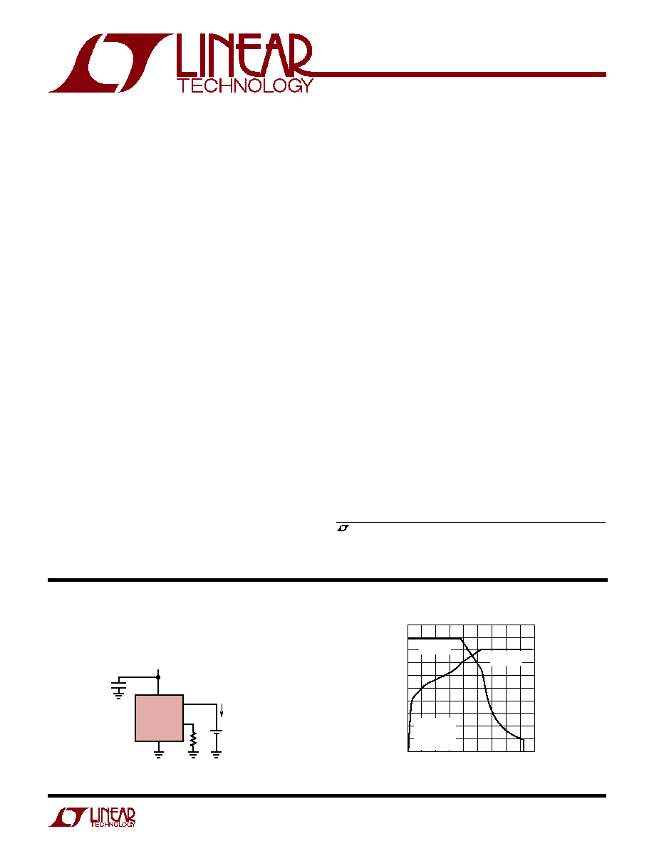
V
CC
1.69k
4.2V
COIN CELL
Li-Ion
BATTERY
4054l42 TA01
LTC4054L-4.2
1
µ
F
V
IN
4.5V TO 6.5V
BAT
4
3
90mA
5
2
PROG
GND
90mA Li-Ion Single Coin Cell Charger
TIME (HOURS)
0
CHARGE CURRENT (mA)
100
90
80
70
60
50
40
30
20
10
0
BATTERY VOLTAGE (V)
4.4
4.3
4.2
4.1
4.0
3.9
3.8
3.7
3.6
3.5
3.4
0.5
1.0 1.25
2.25
4054l42 TA01b
0.25
0.75
1.5 1.75 2.0
CONSTANT
CURRENT
CONSTANT
VOLTAGE
V
CC
= 5V
JA
= 130
∞
C/W
R
PROG
= 1.69k
T
A
= 25
∞
C
Complete Charge Cycle (130mAh Battery)
FEATURES
DESCRIPTIO
U
APPLICATIO S
U
TYPICAL APPLICATIO
U
2
LTC4054L-4.2
4054l42f
(Note 1)
Input Supply Voltage (V
CC
) ....................... ≠0.3V to 10V
PROG ............................................. ≠ 0.3V to V
CC
+ 0.3V
CHRG ........................................................ ≠0.3V to 10V
BAT ............................................................. ≠ 0.3V to 7V
BAT Short-Circuit Duration .......................... Continuous
BAT Pin Current ................................................. 200mA
PROG Pin Current ................................................ 1.5mA
Maximum Junction Temperature .......................... 125
∞
C
Operating Temperature Range (Note 2) .. ≠ 40
∞
C to 85
∞
C
Storage Temperature Range ................. ≠ 65
∞
C to 125
∞
C
Lead Temperature (Soldering, 10 sec).................. 300
∞
C
T
JMAX
= 125
∞
C,
JA
= 80
∞
C/ W TO 150
∞
C/W
DEPENDING ON PC BOARD LAYOUT (NOTE 3)
ORDER PART
NUMBER
S5 PART MARKING
LTC4054LES5-4.2
LTAFA
SYMBOL
PARAMETER
CONDITIONS
MIN
TYP
MAX
UNITS
V
CC
Supply Voltage
q
4.25
6.5
V
I
CC
Supply Current
Charge Mode (Note 4), R
PROG
= 1k
q
1200
2000
µ
A
Standby Mode (Charge Terminated)
q
200
500
µ
A
Shutdown Mode (R
PROG
Not Connected,
q
25
50
µ
A
V
CC
< V
BAT
, or V
CC
< V
UV
)
V
FLOAT
Regulated Output (Float) Voltage
0
∞
C
T
A
85
∞
C, I
BAT
= 40mA
4.158
4.2
4.242
V
I
BAT
BAT Pin Current
R
PROG
= 15k, Current Mode
q
9.3
10
10.7
mA
R
PROG
= 1k, Current Mode
q
142.5
150
157.5
mA
Standby Mode, V
BAT
= 4.2V
q
0
≠2.5
≠6
µ
A
Shutdown Mode (R
PROG
Not Connected)
±
1
±
2
µ
A
Sleep Mode, V
CC
= 0V
±
1
±
2
µ
A
I
TRIKL
Trickle Charge Current
V
BAT
< V
TRIKL
, R
PROG
= 1k (I
BAT
= 150mA)
q
5
15
25
mA
V
TRIKL
Trickle Charge Threshold Voltage
R
PROG
= 15k, V
BAT
Rising
2.8
2.9
3
V
V
TRHYS
Trickle Charge Hysteresis Voltage
R
PROG
= 15k
60
80
110
mV
V
UV
V
CC
Undervoltage Lockout Threshold Voltage
From V
CC
Low to High
q
3.7
3.8
3.92
V
V
UVHYS
V
CC
Undervoltage Lockout Hysteresis Voltage
q
150
200
300
mV
V
MSD
Manual Shutdown Threshold Voltage
PROG Pin Rising
q
1.15
1.21
1.30
V
PROG Pin Falling
q
0.9
1.0
1.1
V
V
ASD
V
CC
≠ V
BAT
Lockout Threshold Voltage
V
CC
from Low to High
70
100
140
mV
V
CC
from High to Low
5
30
50
mV
I
TERM
C/10 Termination Current Threshold
R
PROG
= 15k (I
BAT
= 10mA) (Note 5)
q
0.085
0.10
0.115
mA/mA
R
PROG
= 1k (I
BAT
= 150mA) (Note 5)
q
0.088
0.10
0.112
mA/mA
V
PROG
PROG Pin Voltage
R
PROG
= 1k, Current Mode
q
0.93
1
1.07
V
I
CHRG
CHRG Pin Weak Pull-Down Current
V
CHRG
= 5V
8
20
35
µ
A
V
CHRG
CHRG Pin Output Low Voltage
I
CHRG
= 5mA
0.35
0.6
V
V
RECHRG
Recharge Battery Hysteresis Voltage
V
FLOAT
≠ V
RECHRG
100
150
200
mV
The
q
denotes specifications which apply over the full operating
temperature range, otherwise specifications are at T
A
= 25
∞
C. V
CC
= 5V, unless otherwise noted.
ABSOLUTE AXI U RATI GS
W
W
W
U
PACKAGE/ORDER I FOR ATIO
U
U
W
ELECTRICAL CHARACTERISTICS
Consult LTC Marketing for parts specified with wider operating temperature ranges.
CHRG 1
GND 2
TOP VIEW
S5 PACKAGE
5-LEAD PLASTIC TSOT-23
BAT 3
5 PROG
4 V
CC

3
LTC4054L-4.2
4054l42f
The
q
denotes specifications which apply over the full operating
temperature range, otherwise specifications are at T
A
= 25
∞
C. V
CC
= 5V, unless otherwise noted.
ELECTRICAL CHARACTERISTICS
SYMBOL
PARAMETER
CONDITIONS
MIN
TYP
MAX
UNITS
T
LIM
Junction Temperature in Constant
120
∞
C
Temperature Mode
R
ON
Power FET "ON" Resistance
1.5
(Between V
CC
and BAT)
t
SS
Soft-Start Time
I
BAT
= 0 to I
BAT
=150V/R
PROG
100
µ
s
t
RECHARGE
Recharge Comparator Filter Time
V
BAT
High to Low
0.75
2
4.5
ms
t
TERM
Termination Comparator Filter Time
I
BAT
Drops Below I
CHG
/10
400
1000
2500
µ
s
I
PROG
PROG Pin Pull-Up Current
1.5
3
5
µ
A
Note 1: Absolute Maximum Ratings are those values beyond which the life
of the device may be impaired.
Note 2: The LTC4054LE-4.2 is guaranteed to meet performance specifica-
tions from 0
∞
C to 70
∞
C. Specifications over the ≠40
∞
C to 85
∞
C operating
temperature range are assured by design, characterization and correlation
with statistical process controls.
Note 3: See Thermal Considerations.
Note 4: Supply current includes PROG pin current (
1mA) but does not
include any current delivered to the battery through the BAT pin.
Note 5: I
TERM
is expressed as a fraction of measured full charge current
with indicated PROG resistor.
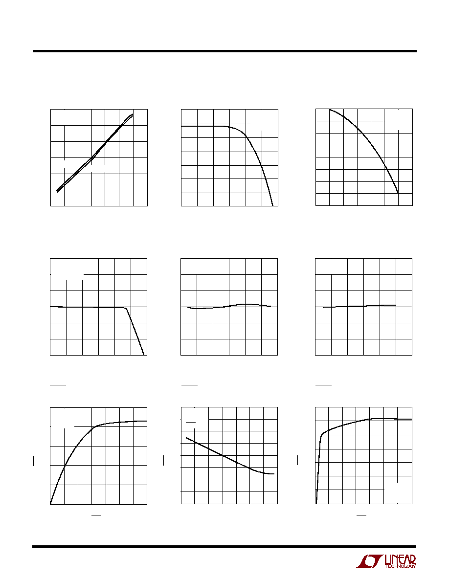
TYPICAL PERFOR A CE CHARACTERISTICS
U
W
PROG Pin Voltage vs Supply
Voltage (Constant Current Mode)
V
CC
(V)
4
V
PROG
(V)
0.9975
1.0000
1.0025
5.5
6.5
4054L G01
0.9950
0.9925
0.9900
4.5
5
6
1.0050
1.0075
1.0100
7
V
CC
= 5V
V
BAT
= 4V
T
A
= 25
∞
C
R
PROG
= 1k
R
PROG
= 15k
TEMPERATURE (
∞
C)
≠50
V
PROG
(V)
0.9975
1.0000
1.0025
25
75
4054L G02
0.9950
0.9925
0.9900
≠25
0
50
1.0050
1.0075
1.0100
100
V
CC
= 5V
V
BAT
= 4V
R
PROG
= 1k
V
PROG
(V)
0
0
I
BAT
(mA)
30
60
90
120
150
180
0.25
0.5
0.75
1
4054L G03
1.25
V
CC
= 5V
R
PROG
= 1k
T
A
= 25
∞
C
PROG Pin Voltage vs Temperature
(Constant Current Mode)
Charge Current
vs PROG Pin Voltage
4
LTC4054L-4.2
4054l42f
TYPICAL PERFOR A CE CHARACTERISTICS
U
W
PROG Pin Pull-Up Current vs
Temperature and Supply Voltage
PROG Pin Current vs PROG Pin
Voltage (Pull-Up Current)
TEMPERATURE (
∞
C)
≠50
I
PROG
(
µ
A)
3.3
3.5
3.7
25
75
4054L G04
3.1
2.9
≠25
0
50
100
125
2.7
2.5
V
BAT
= 4.3V
V
PROG
= 0V
V
CC
= 6.5V
V
CC
= 4.2V
V
PROG
(V)
2.0
3.5
3.0
2.5
2.0
1.5
1.0
0.5
0
2.3
2.5
4054L G05
2.1
2.2
2.4
2.6
I
PROG
(
µ
A)
V
CC
= 5V
V
BAT
= 4.3V
T
A
= 25
∞
C
V
PROG
(V)
2
I
PROG
(
µ
A)
≠50
3.5
4054L G06
≠200
≠300
2.5
3
4
≠350
≠400
0
≠100
≠150
≠250
4.5
5
5.5
V
CC
= 5V
V
BAT
= 4.3V
T
A
= 25
∞
C
PROG Pin Current vs PROG Pin
Voltage (Clamp Current)
Regulated Output (Float) Voltage
vs Charge Current
I
BAT
(mA)
0
4.14
V
FLOAT
(V)
4.16
4.18
4.20
4.22
4.26
30
60
90
120
4054L G07
150
180
4.24
V
CC
= 5V
R
PROG
= 600
T
A
= 25
∞
C
Regulated Output (Float) Voltage
vs Temperature
TEMPERATURE (
∞
C)
≠50
4.185
V
FLOAT
(V)
4.190
4.195
4.200
4.205
4.215
≠25
0
25
50
4054L G08
75
100
4.210
V
CC
= 5V
R
PROG
= 1k
Regulated Output (Float) Voltage
vs Supply Voltage
V
CC
(V)
4
4.185
V
FLOAT
(V)
4.190
4.195
4.200
4.205
4.215
4.5
5
5.5
6
4054L G09
6.5
7
4.210
R
PROG
= 1k
T
A
= 25
∞
C
CHRG Pin I-V Curve
(Strong Pull-Down State)
V
CHRG
(V)
0
1
0
I
CHRG
(mA)
10
25
2
4
5
4054L G10
5
20
15
3
6
7
V
CC
= 5V
V
BAT
= 4V
T
A
= 25
∞
C
CHRG Pin Current vs Temperature
(Strong Pull-Down State)
TEMPERATURE (
∞
C)
≠ 50
I
CHRG
(mA)
18
25
4054L G11
12
8
≠ 25
0
50
6
4
20
16
14
10
75
100
125
V
CC
= 5V
V
BAT
= 4V
V
CHRG
= 1V
CHRG Pin I-V Curve
(Weak Pull-Down State)
V
CHRG
(V)
0
16
18
22
3
5
4054L G12
14
12
1
2
4
6
7
10
8
20
I
CHRG
(
µ
A)
V
CC
= 5V
V
BAT
= 4.3V
T
A
= 25
∞
C
5
LTC4054L-4.2
4054l42f
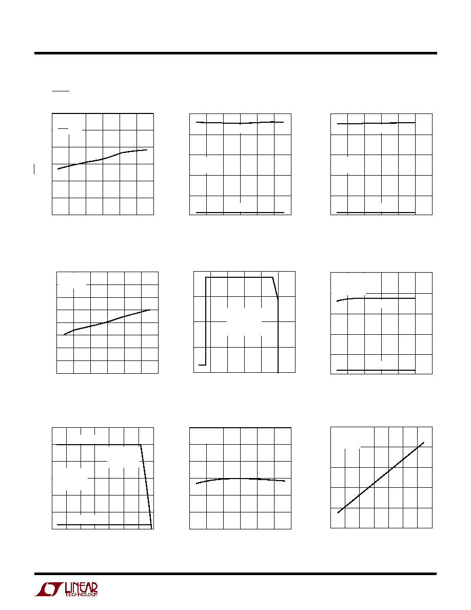
TYPICAL PERFOR A CE CHARACTERISTICS
U
W
CHRG Pin Current vs Temperature
(Weak Pull-Down State)
Trickle Charge Current
vs Temperature
Trickle Charge Current
vs Supply Voltage
Trickle Charge Threshold
vs Temperature
Charge Current vs Battery Voltage
Charge Current
vs Ambient Temperature
Recharge Voltage Threshold
vs Temperature
Power FET "ON" Resistance
vs Temperature
TEMPERATURE (
∞
C)
≠50
10
I
CHRG
(
µ
A)
13
16
19
22
28
≠25
0
25
50
4054L G13
75
100
25
V
CC
= 5V
V
BAT
= 4.3V
V
CHRG
= 5V
TEMPERATURE (
∞
C)
≠50
0
I
TRKL
(mA)
3
6
9
12
15
≠25
0
25
50
4054L G14
75
100
R
PROG
= 1k
R
PROG
= 15k
V
CC
= 5V
V
BAT
= 2.5V
V
CC
(V)
4
0
I
TRKL
(mA)
3
6
9
12
15
4.5
5
5.5
6
4054L G15
6.5
7
R
PROG
= 1k
R
PROG
= 15k
V
BAT
= 2.5V
T
A
= 25
∞
C
TEMPERATURE (
∞
C)
≠50
V
TRKL
(V)
25
75
4054L G16
≠25
0
50
2.950
2.925
2.900
2.875
2.850
2.825
2.800
2.975
3.000
100
V
CC
= 5V
R
PROG
= 1k
V
BAT
(V)
2.7
0
I
BAT
(mA)
40
80
120
160
3.0
3.3
3.6
3.9
4054L G17
4.2
4.5
V
CC
= 5V
R
PROG
= 1k
T
A
= 25
∞
C
JA
= 125
∞
C/W
Charge Current vs Supply Voltage
V
CC
(V)
4
0
I
BAT
(mA)
40
80
120
160
200
4.5
5
5.5
6
4054L G18
6.5
7
R
PROG
= 1k
R
PROG
= 15k
V
BAT
= 4V
T
A
= 25
∞
C
JA
= 125
∞
C/W
TEMPERATURE (
∞
C)
≠50
I
BAT
(mA)
120
150
180
25
75
4054L G19
90
60
≠25
0
50
100
125
30
0
R
PROG
= 1k
R
PROG
= 15k
V
BAT
= 4V
V
CC
= 5V
JA
= 125
∞
C/W
ONSET OF
THERMAL
REGULATION
TEMPERATURE (
∞
C)
≠50
3.99
V
RECHRG
(V)
4.01
4.03
4.05
4.07
4.11
≠25
0
25
50
4054L G20
75
100
4.09
V
CC
= 5V
R
PROG
= 1k
TEMPERATURE (
∞
C)
≠50
≠25
0.8
R
DS(ON)
(m
)
1.2
1.8
0
50
75
4054L G21
1.0
1.6
1.4
25
100
125
V
CC
= 4.1V
V
BAT
= 4V
R
PROG
= 1k