Äîêóìåíòàöèÿ è îïèñàíèÿ www.docs.chipfind.ru
LTC1998
1
1998f
APPLICATIO S
U
FEATURES
ThinSOT is a trademark of Linear Technology Corporation.
s
Lithium-Ion Battery-Powered Equipment
PDAs
Cell Phones
Handheld Instruments
Battery Packs
Pagers
Palm Top Computers
POS Terminals
s
High Accuracy Trip Voltage: 1% Max Error Using
External 1% Resistors
s
Adjustable Threshold Voltage and Hysteresis
s
Quiescent Current: 2.5
µ
A Typ
s
Output Swings Rail-to-Rail
s
Thresholds Programmable from 2.5V to 3.25V
s
Output State Guaranteed for V
BATT
1.5V
s
Low Profile (1mm) ThinSOT
TM
Package
2.5
µ
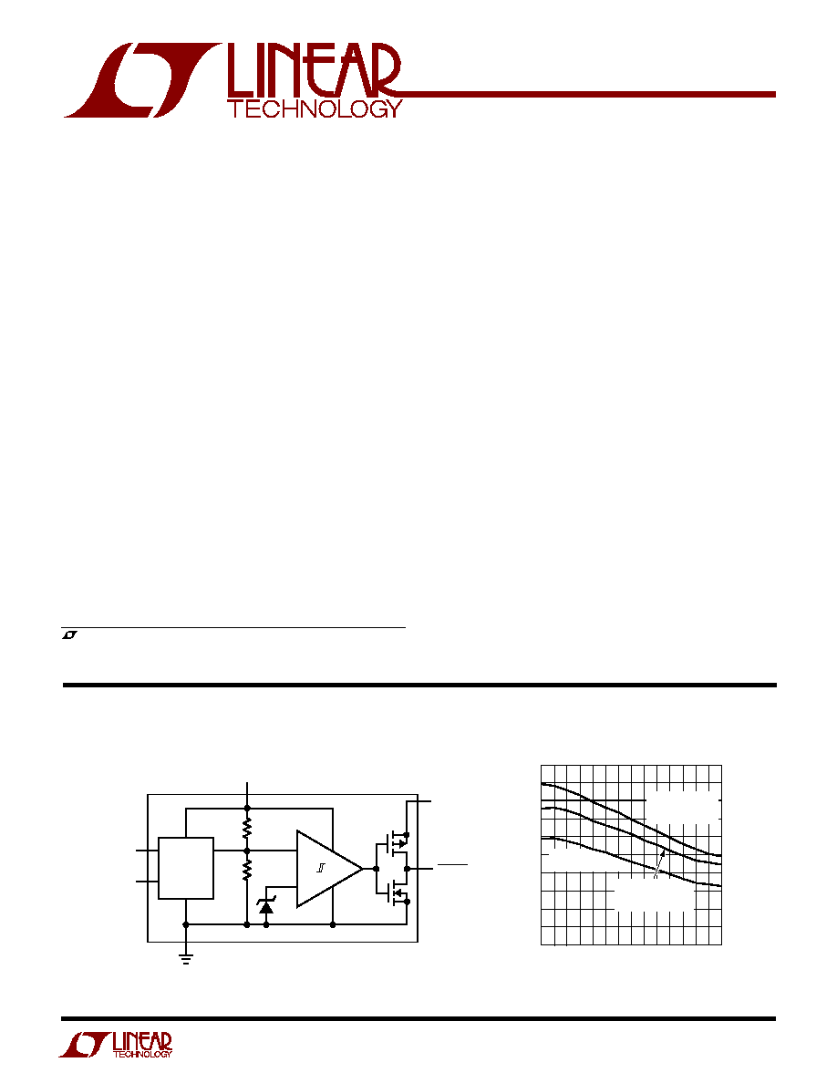
A, 1% Accurate
SOT-23 Comparator and Voltage
Reference for Battery Monitoring
The LTC
®
1998 is a micropower comparator and a preci-
sion adjustable reference in a 6-pin SOT-23 package that
is optimized for lithium-ion low battery detection circuits.
The LTC1998 features a voltage detection circuit with an
adjustable threshold voltage and hysteresis. The thresh-
old voltage can be programmed from 2.5V to 3.25V with
two external resistors. A 10mV to 750mV hysteresis can
be added with a third external resistor.
A proprietary internal architecture maintains 1% thresh-
old voltage accuracy over temperature with low cost 1%
external resistors.
A separate power supply pin, V
LOGIC
, allows the battery-
low logic output to operate below the battery voltage,
allowing compatibility with low voltage microprocessors
without a pull-up resistor. Power supply glitches are
eliminated by preventing the cross-conducting current
which occurs when the output changes state.
The LTC1998 operates with battery or supply voltages up
to 5.5V and its battery-low output is valid for battery
voltages above 1.5V.
, LTC and LT are registered trademarks of Linear Technology Corporation.
Threshold Voltage Error vs Temperature
DESCRIPTIO
U
1998 BD
THRESHOLD
ADJUST
V
HYST.A
V
TH.A
BATT
V
LOGIC
BATTLO
1.1R
R
1.2V
BLOCK DIAGRA
W
TEMPERATURE (
°
C)
45
15
55
1998
G05
25
5
35
75
95
1.0
0.9
0.8
0.7
0.6
0.5
0.4
0.3
0.2
0.1
0
% ERROR
V
TH.A
SET BY 1%
EXTERNAL R,
THRESHOLD = 3V
V
TH.A
=
1V
THRESHOLD = 3V
V
TH.A
SHORTED
TO GROUND,
THRESHOLD = 2.5V
LTC1998
2
1998f
Total Supply Voltage (BATT or V
LOGIC
to GND) ......... 6V
Voltage
V
TH.A
, V
H.A ...........................
BATT + 0.3V to GND 0.3V
BATTLO ........................ V
LOGIC
+ 0.3V to GND 0.3V
Operating Temperature Range (Note 3) ...40
°
C to 85
°
C
Specified Temperature Range (Note 4)
LTC1998C ...........................................40
°
C to 85
°
C
LTC1998I .............................................40
°
C to 85
°
C
Storage Temperature Range ................. 65
°
C to 150
°
C
Lead Temperature (Soldering, 10 sec).................. 300
°
C
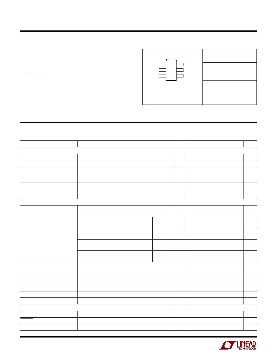
ORDER PART
NUMBER
S6 PART MARKING*
T
JMAX
= 150
°
C,
JA
= 250
°
C/W
LTTY
LTC1998CS6
LTC1998IS6
ABSOLUTE AXI U
RATI GS
W
W
W
U
PACKAGE/ORDER I FOR ATIO
U
U
W
(Note 1)
ELECTRICAL CHARACTERISTICS
The
q
denotes the specifications which apply over the full operating
temperature range, otherwise specifications are at T
A
= 25
°
C. V
GND
= 0V, unless otherwise noted.
Consult LTC Marketing for parts specified with wider operating temperature ranges.
6 BATTLO
5 V
LOGIC
4 V
H.A
BATT 1
TOP VIEW
S6 PACKAGE
6-LEAD PLASTIC SOT-23
GND 2
V
TH.A
3
*The temperature grades are indentified by a label on the shipping container.
PARAMETER
CONDITIONS
MIN
TYP
MAX
UNITS
Power Supply
Supply Voltage Range-BATT
q
1.5
5.5
V
Supply Voltage Range-V
LOGIC
q
1
V
BATT
V
Supply Current, V
BATT
= 3V,
T
A
= 25
°
C
2.5
3.5
µ
A
V
TH.A
= 1.5V
LTC1998CS6
q
4.2
µ
A
LTC1998IS6
q
4.5
µ
A
Supply Current, V
BATT
= 5.5V,
T
A
= 25
°
C
3
4.3
µ
A
V
TH.A
= 1.5V
LTC1998CS6
q
5.2
µ
A
LTC1998IS6
q
5.5
µ
A
Monitor
Threshold Accuracy
V
BATT.Th
= 2.5V, Pin 3 Shorted to Ground
0.6
0.85
%
q
0.8
1
%
V
BATT.Th
= 3V, Pin 3 Driven by Precision
LTC1998C
q
0.5
0.61
%
Voltage Source to 1V
LTC1998I
q
0.6
0.71
%
V
BATT.Th
= 3V, V
TH.A
= 1V (Note 5)
LTC1998C
q
0.8
1
%
Programmed with 1% Max External Resistors
LTC1998I
q
0.9
1.1
%
V
BATT.Th
= 3.25V, Pin 3 Diven by Precision
LTC1998C
q
0.6
0.65
%
Voltage Source to 1.5V
LTC1998I
q
0.7
0.85
%
V
BATT.Th
= 3.25V, V
TH.A
= 1.5V (Note 5)
LTC1998C
q
0.9
1.1
%
Programmed with1% Max External Resistors
LTC1998I
q
1
1.3
%
Hysteresis Accuracy
V
HYST
250mV
q
5
5
mV
250mV
V
HYST
750mV
q
±
5
mV
Allowable Hysteresis Range (Note 2)
q
10
750
mV
Propagation Delay
C
OUT
= 100pF, Overdrive = 10mV
350
µ
s
Overdrive = 100mV
150
µ
s
Threshold Adjust Pin Leakage, I
TH.A
V
TH.A
1.5V
q
0.01
1
nA
Hysteresis Adjust Pin Leakage, I
H.A
V
H.A
1.5V
q
0.01
1
nA
Output
BATTLO High Voltage
I
OUT
= 1mA
q
V
LOGIC
0.3
V
BATTLO Low Voltage
I
OUT
= 1mA, V
BATT
2V
q
0.2
V
BATTLO Low Voltage
I
OUT
= 0.25mA, V
BATT
= 1V
q
0.3
V

LTC1998
3
1998f
TYPICAL PERFOR A CE CHARACTERISTICS
U
W
THRESHOLD ADJUST VOLTAGE (V)
0
THRESHOLD VOLTAGE (V)
3.5
3.0
2.5
1998 G03
0.5
1.0
1.5
LOW BATTERY THRESHOLD VOLTAGE (V)
2.5
AVAILABLE HYSTERESIS (mV)
750
500
250
0
1998 G04
2.75
3.0
3.25
Quiescent Supply Current vs
Supply Voltage
Quiescent Supply Current vs
Temperature
Threshold Voltage vs Threshold
Adjust Voltage
Available Hysteresis vs
Threshold Voltage
Threshold Voltage Error vs
Temperature
Input Current vs Temperature
SUPPLY VOLTAGE (V)
0.5 1.0 1.5 2.0 2.5 3.0 3.5 4.0 4.5 5.0 5.5 6.0
SUPPLY CURRENT (
µ
A)
3.5
3.0
2.5
2.0
1.5
1.0
0.5
0
1998 G01
T
A
= 25
°
C
V
LOGIC
= V
BATT
V
TH.A
= 0V
V
TH.A
= 1.5V
TEMPERATURE (
°
C)
50
30
10
10
30
50
70
90
SUPPLY CURRENT (
µ
A)
1998 G02
3.5
3.0
2.5
2.0
1.5
1.0
0.5
0
V
BATT
= V
LOGIC
= 3V
V
TH.A
= 1.5V
TEMPERATURE (
°
C)
45
15
55
1998
G05
25
5
35
75
95
1.0
0.9
0.8
0.7
0.6
0.5
0.4
0.3
0.2
0.1
0
% ERROR
V
TH.A
SET BY 1%
EXTERNAL R,
THRESHOLD = 3V
V
TH.A
=
1V
THRESHOLD = 3V
V
TH.A
SHORTED
TO GROUND,
THRESHOLD = 2.5V
TEMPERATURE (
°
C)
35
0.1
INPUT CURRENT V
TH.A
, V
H.A
(pA)
1
100
1000
10000
55
75
85
125
1998 G06
10
45
65
95 105 115
V
IN
= 1.5V
V
IN
= 0.5V
V
IN
= 1V
Note 1: Absolute Maximum Ratings are those values beyond which the life
of a device may be impaired.
Note 2: Maximum allowable hysteresis depends on desired trip voltages.
See application notes for details.
Note 3: LTC1998C and LTC1998I are guaranteed functional over the
operating temperature range of 40
°
C to 85
°
C.
Note 4: The LTC1998C is guaranteed to meet specified performance from
0
°
C to 70
°
C. The LTC1998C is designed, characterized and expected to
meet specified performance from 40
°
C to 85
°
C but is not tested or QA
sampled at these temperatures. The LTC1998I is guaranteed to meet
specified performance from 40
°
C to 85
°
C.
Note 5: This parameter is not 100% tested.
ELECTRICAL CHARACTERISTICS

LTC1998
4
1998f
How to Calculate the External Resistor Values
The LTC1998 is a low battery warning indicator and is
especially designed for monitoring the voltage of single-
cell Lithium-Ion batteries. The LTC1998 compares its
supply pin (BATT) to an accurate internal reference; if the
battery voltage falls below the programmed low battery
QUICK DESIG GUIDE
U
U
U
U
PI FU CTIO S
BATT (Pin 1): Battery Voltage to be monitored. Supply
current is also drawn from this pin. Board layout should
connect this pin to the battery(+) terminal, through a trace
that does not conduct load current.
GND (Pin 2): Ground should be connected to the battery
() terminal through a trace that does not conduct load
return current.
V
TH.A
(Pin 3): Threshold Adjust Pin. Adjusts the low
battery threshold voltage, V
BATT.Th
= 2.5V + (V
TH.A
/2).
V
TH.A
can be supplied by a voltage source or a resistor
divider.
V
H.A
(Pin 4): Hysteresis Adjust. Hysteresis threshold
voltage V
TH2
= 2.5V + (V
H.A
/2). V
H.A
can be supplied by a
voltage source or resistor divider. V
H.A
must always be
programmed to a higher potential than V
TH.A
. Hysteresis
voltage, V
HYST
= V
TH2
V
BATT.Th
.
V
LOGIC
(Pin 5): Positive Supply Voltage for Output Driver.
This voltage can be driven from an external logic supply or
tied to BATT.
BATTLO (Pin 6): Output of Comparator. Low for BATT <
V
BATT.Th
(low battery threshold voltage). Output state
guaranteed for V
BATT
1.5V.
Output Low Voltage vs Load
Current
Output High Voltage vs Load
Current
Output Short-Circuit Current vs
Supply Voltage
OUTPUT SINK CURRENT (mA)
1
OUTPUT VOLTAGE (V)
1998 G07
2
3
4
5
0.6
0.4
0.2
0
T
A
= 25
°
C
V
LOGIC
= V
BATT
= 3V
T
A
= 40
°
C
T
A
= 85
°
C
T
A
= 25
°
C
OUTPUT SOURCE CURRENT (mA)
1
OUTPUT VOLTAGE RELATIVE TO V
BATT
(mV)
1998 G08
2
3
4
5
0
50
100
150
200
250
T
A
= 25
°
C
V
LOGIC
= V
BATT
T
A
= 85
°
C
T
A
= 40
°
C
BATT = 3V
BATT = 5V
T
A
= 25
°
C
T
A
= 40
°
C
T
A
= 85
°
C
T
A
= 25
°
C
SUPPLY VOLTAGE (V)
1.0 1.5
2.5
3.5
4.5
5.5
CURRENT (mA)
120
100
80
60
40
20
0
2.0
3.0
4.0
5.0
1998 G09
6.0
SOURCE CURRENT,
BATTLO SHORTED TO GND
SINK CURRENT,
BATTLO SHORTED
TO V
LOGIC
TA = 25
°
C
V
BATT
= V
LOGIC
TYPICAL PERFOR A CE CHARACTERISTICS
U
W
threshold voltage of the LTC1998, the battery low pin
(BATTLO) will change state, from high to low, to indicate
a low battery condition. The low battery threshold voltage
is programmed via the voltage threshold adjust pin (V
TH.A
).
A hysteresis adjust pin (V
H.A
) will add hysteresis to the
programmed value of the low battery threshold voltage.

LTC1998
5
1998f
1998 F01
LTC1998
R1
1%
R2
1%
R3
1%
V
H.A
V
TH.A
BATT
V
LOGIC
BATTLO
4
3
2
1
5
6
REGULATOR
µ
P
Li-Ion
GND
0.1
µ
F
1.5V TO 4.2V
V
LOGIC
+
Figure 1. Low Battery Threshold Detector with Hysteresis
Example 1: A system using a 4.2V (fully charged) Lithium-
Ion battery requires a low battery threshold of 2.7V,
100mV hysteresis and can allow up to 4.2
µ
A maximum
resistor current.
R
TOTAL
= 1M
, R1 = 786k, R2 = 66k and R3 = 148k
Choose standard 1% values.
R1 = 787k, R2 = 66.5k, R3 = 147k
QUICK DESIG GUIDE
U
Typical Application
Table 1: Design Equations for R1, R2, R3, Figure 1
Choose desired values for:
· V
BATT.Th
: Low Battery Threshold Voltage
· V
HYST
: Hysteresis Voltage
· I
R
: Max Allowable Resistor Current
Solve:
R
R
R
R
V
I
R
R
V
V
V
R
R
V
V
R
R
R
R
R
TOTAL
R
TOTAL
BATT Th
HYST
TOTAL
BATT Th
TOTAL
= +
+
=
=
+
=
=
1
2
3
4 2
1
5
1
2
5
1
1
3
1
2
.
·
·
.
.
LOW BATTERY THRESHOLD VOLTAGE AND
HYSTERESIS ADJUST
Low Battery Threshold Voltage Adjustment, Pin 3
The low battery threshold voltage is the battery voltage
which will trip the (BATTLO) pin high to low. It should be
adjusted via the threshold adjust pin (V
TH.A
). This is a high
input impedance pin that senses an externally applied
voltage and programs the low battery threshold voltage
(V
BATT.Th
). The V
TH.A
pin is designed to accommodate
voltages from 0V to 1.5V with respect to ground. This
allows the low battery threshold voltage to be set to any
voltage between 2.5V and 3.25V, that is:
V
V
V
BATT Th
TH A
.
.
.
(
)
=
+
2 5
2
APPLICATIO S I FOR ATIO
W
U
U
U
For instance, if the applied voltage at pin 3, V
TH.A
, is 1V the
LTC1998 will indicate a low battery condition when the
battery voltage pin (BATT) falls below 3V.
The voltage at the threshold adjust pin (V
TH.A
) can be set
with any voltage source. This pin allows a continuous time
adjustment, that is, the low battery threshold voltage may
be changed at any time. The high input impedance of the
V
TH.A
pin allows the use of a high valued resistive divider
(to minimize current drain) from the battery to set the
battery low threshold voltage, Figure 2.
Figure 2. Resistor Divider Sets Threshold
1998 F02
LTC1998
R1
R2
V
TH.A
BATT
+
Li-Ion
1
2
3