
1
LTC2054/LTC2055
20545fa
Single/Dual
Micropower Zero-Drift
Operational Amplifiers
s
Thermocouple Amplifiers
s
Electronic Scales
s
Medical Instrumentation
s
Strain Gauge Amplifiers
s
High Resolution Data Acquisition
s
DC Accurate RC Active Filters
s
Low Side Current Sense
s
Battery-Powered Systems
s
Supply Current 150
µ
A (Max per Amplifier)
Guaranteed Over Temperature
s
Offset Voltage 3
µ
V (Max)
s
Offset Voltage Drift 30nV/
∞
C (Max)
s
Common Mode Input Range from V
≠
to V
+
≠0.5V
s
Output Swings Rail-to-Rail
s
Voltage Gain: 140dB (Typ)
s
PSRR and CMRR: 130dB (Typ)
s
Input Bias Current: 1pA (Typ, 25
∞
C)
s
Noise: 1.6
µ
V
P-P
(0.01Hz to 10Hz Typ)
s
Supply Operation:
2.7V to 6V (LTC2054/LTC2055)
2.7V to
±
5.5V (LTC2054HV/LTC2055HV)
s
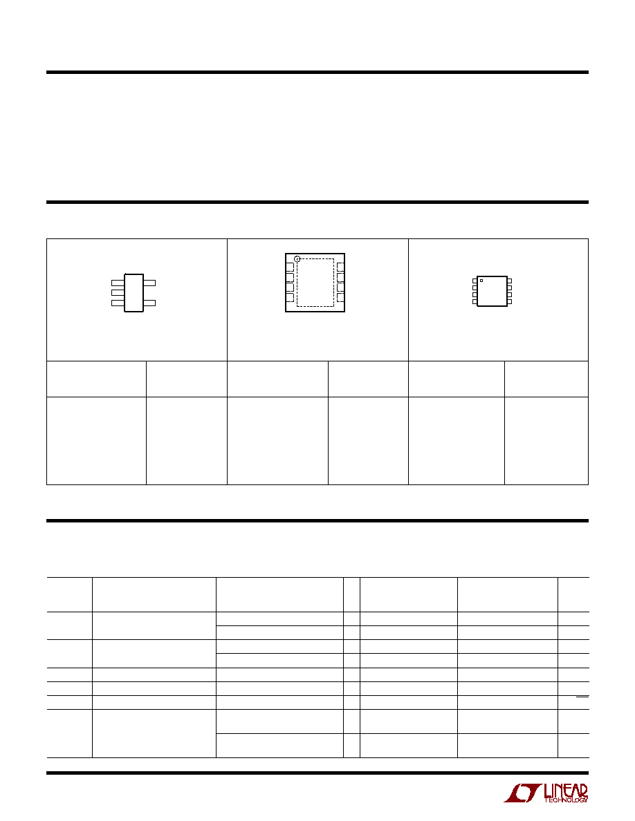
Low Profile (1mm) SOT-23, MS8 and
3mm
◊
3mm
◊
0.8mm DFN Packages
The LTC
Æ
2054/LTC2055 are low power, low noise single/
dual zero-drift operational amplifiers available in the SOT-23
(ThinSOT
TM
) and MS8 packages. For space limited appli-
cations, the LTC2055 is also available in a 3mm
◊
3mm
◊
0.8mm dual fine pitch leadless package (DFN). They
operate from a single 2.7V minimum supply and support
±
5V applications. The current consumption is typically
150
µ
A for the LTC2054 and 130
µ
A/amp for the LTC2055.
The LTC2054/LTC2055, despite their miniature size, fea-
ture uncompromising DC performance. The typical input
offset voltage and offset drift are 0.5
µ
V and 25nV/
∞
C. The
almost zero DC offset and drift are supported with a power
supply rejection ratio (PSRR) and common mode rejec-
tion ratio (CMRR) of more than 130dB.
The input common mode voltage ranges from the negative
supply up to typically 0.5V from the positive supply. The
open-loop gain is typically 140dB. The LTC2054/LTC2055
also feature a 1.6
µ
V
P-P
DC to 10Hz noise and a 500kHz
gain-bandwidth product.
Supply Current (per Amplifier)
≠48V Low Side Precision Current Sense
, LTC and LT are registered trademarks of Linear Technology Corporation.
FEATURES
DESCRIPTIO
U
TYPICAL APPLICATIO
U
APPLICATIO S
U
ThinSOT is a trademark of Linear Technology Corporation
≠
+
0.01
µ
F
0.1
µ
F
0.1
µ
F
0.003
1% 3W
39k
BZX84C5V1
V
Z
= 5.1
≠48V SUPPLY
I
SENSE
,
V
SENSE
≠
+
100
1%
LTC2054
20545 TA01
≠
+
10k
1%
5V
V
OUT
= 100V
SENSE
LTC2054
≠48V LOAD
Q1
ZETEX
ZVN3320F
100
TEMPERATURE (
∞
C)
SUPPLY CURRENT (
µ
A)
20545 TA01b
250
225
200
175
150
125
100
75
50
25
0
≠40
125
25
45
70
85
5
≠15
LTC2054
LTC2055
2
LTC2054/LTC2055
20545fa
5 V
+
4 ≠IN
OUT 1
TOP VIEW
S5 PACKAGE
5-LEAD PLASTIC SOT-23
V
≠
2
+IN 3
1
2
3
4
OUT A
≠IN A
+IN A
V
≠
8
7
6
5
V
+
OUT B
≠IN B
+IN B
TOP VIEW
MS8 PACKAGE
8-LEAD PLASTIC MSOP
TOP VIEW
DD PACKAGE
8-LEAD (3mm
◊
3mm) PLASTIC DFN
UNDERSIDE METAL INTERNALLY
CONNECTED TO V
≠
(PCB CONNECTION OPTIONAL)
5
6
7
8
4
3
2
1
OUT A
≠IN A
+IN A
V
≠
V
+
OUT B
≠IN B
+IN B
Total Supply Voltage (V
+
to V
≠
)
LTC2054/LTC2055 .................................................. 7V
LTC2054HV/LTC2055HV ....................................... 12V
Input Voltage ........................ (V
+
+ 0.3V) to (V
≠
≠ 0.3V)
Input Current ......................................................
±
10mA
Output Short-Circuit Duration ......................... Indefinite
Operating Temperature Range ............. ≠ 40
∞
C to 125
∞
C
Specified Temperature Range (Note 3) ≠ 40
∞
C to 125
∞
C
Storage Temperature Range ................ ≠ 65
∞
C to 150
∞
C
DD Package ...................................... ≠ 65
∞
C to 125
∞
C
Lead Temperature (Soldering, 10 sec)................. 300
∞
C
(Note 1)
ORDER PART
NUMBER*
ABSOLUTE AXI U RATI GS
W
W
W
U
PACKAGE/ORDER I FOR ATIO
U
U
W
T
JMAX
= 150
∞
C,
JA
= 200
∞
C/W
T
JMAX
= 125
∞
C,
JA
= 160
∞
C/W, NOTE 5
DD PART
MARKING
LTC2055CDD
LTC2055HVCDD
LTC2055IDD
LTC2055HVIDD
LTC2055HDD
LTC2055HVHDD
ORDER PART
NUMBER*
MS8 PART
MARKING
LTC2055CMS8
LTC2055HVCMS8
LTC2055IMS8
LTC2055HVIMS8
LTC2055HMS8
LTC2055HVHMS8
*The temperature grade (C, I or H) is indicated on the shipping container. Consult LTC Marketing for parts specified with wider operating temperature
ranges.
T
JMAX
= 150
∞
C,
JA
= 250
∞
C/W
ORDER PART
NUMBER*
S5 PART
MARKING
LTC2054CS5
LTC2054HVCS5
LTC2054IS5
LTC2054HVIS5
LTC2054HS5
LTC2054HVHS5
LTAGB
LTAGD
LTAGB
LTAGD
LTAGB
LTAGD
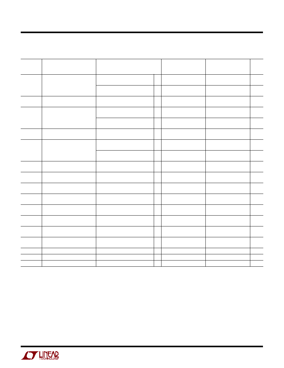
(LTC2054/LTC2055, LTC2054HV/LTC2055HV) The
q
denotes the
specifications which apply over the full operating temperature range, otherwise specifications are at T
A
= 25
∞
C. V
S
= 3V, 5V
unless otherwise noted. (Note 3)
ELECTRICAL CHARACTERISTICS
LTC2054C/LTC2055C
LTC2054I/LTC2055I
LTC2054H/LTC2055H
SYMBOL
PARAMETER
CONDITIONS
MIN
TYP
MAX
MIN
TYP
MAX
UNITS
I
S
Supply Current (LTC2054)
No Load, V
S
= 3V
q
140
175
140
180
µ
A
No Load, V
S
= 5V
q
150
175
150
180
µ
A
I
S
Supply Current Per Amplifier
No Load, V
S
= 3V
q
130
150
130
155
µ
A
(LTC2055)
No Load, V
S
= 5V
q
135
150
135
155
µ
A
V
OS
Input Offset Voltage
(Note 2)
±
0.5
±
3
±
0.5
±
3
µ
V
V
OS
/
T
Average Input Offset Drift
(Note 2)
q
0.02
±
0.03
0.02
±
0.05
µ
V/
∞
C
Long-Term Offset Drift
50
50
nV/
mo
I
B
Input Bias Current (Note 4)
V
S
= 3V
±
1
±
1
pA
V
S
= 3V
q
±
150
3000
pA
V
S
= 5V
±
1
±
1
pA
V
S
= 5V
q
±
150
3000
pA
LBCW
LBCX
LBCW
LBCX
LBCW
LBCX
LTBCR
LTBCT
LTBCR
LTBCT
LTBCR
LTBCT
3
LTC2054/LTC2055
20545fa
LTC2054C/LTC2055C
LTC2054I/LTC2055I
LTC2054H/LTC2055H
SYMBOL
PARAMETER
CONDITIONS
MIN
TYP
MAX
MIN
TYP
MAX
UNITS
I
OS
Input Offset Current (Note 4)
V
S
= 3V
±
2
±
2
pA
V
S
= 3V
q
±
300
±
700
pA
V
S
= 5V
±
2
±
2
pA
V
S
= 5V
q
±
300
±
700
pA
e
n
Input Noise Voltage
R
S
= 100
, DC to 1Hz
0.6
0.6
µ
V
P-P
R
S
= 100
, DC to 10Hz
1.6
1.6
µ
V
P-P
CMRR
Common Mode Rejection Ratio
V
CM
= GND to V
+
≠ 0.7V
115
130
115
130
dB
V
S
= 3V
q
110
110
dB
V
CM
= GND to V
+
≠ 0.7V
120
130
120
130
dB
V
S
= 5V
q
115
115
dB
PSRR
Power Supply Rejection Ratio
V
S
= 2.7V to 6V
120
130
120
130
dB
q
115
115
dB
A
VOL
Large-Signal Voltage Gain
R
L
= 100k, V
S
= 3V, V
OUT
= V
S
/2
120
135
120
135
dB
q
115
115
dB
R
L
= 100k, V
S
= 5V, V
OUT
= V
S
/2
125
140
125
140
dB
q
120
120
dB
V
OUT
Output Voltage Swing High
R
L
= 5k to GND, V
S
= 3V
2.87
2.89
2.87
2.89
V
R
L
= 5k to GND, V
S
= 3V
q
2.85
2.84
V
R
L
= 5k to GND, V
S
= 5V
4.80
4.83
4.80
4.83
V
R
L
= 5k to GND, V
S
= 5V
q
4.75
4.70
V
R
L
= 100k to GND, V
S
= 3V
2.98
2.99
2.98
2.99
V
R
L
= 100k to GND, V
S
= 3V
q
2.975
2.97
V
R
L
= 100k to GND, V
S
= 5V
4.985
4.99
4.985
4.99
V
R
L
= 100k to GND, V
S
= 5V
q
4.980
4.970
V
V
OUT
Output Voltage Swing Low
R
L
= 5k to GND, V
S
= 3V
2
8
3
8
mV
R
L
= 5k to GND, V
S
= 3V
q
10
10
mV
R
L
= 5k to GND, V
S
= 5V
2
8
3
8
mV
R
L
= 5k to GND, V
S
= 5V
q
10
10
mV
R
L
= 100k to GND, V
S
= 3V
2
8
3
8
mV
R
L
= 100k to GND, V
S
= 3V
q
10
10
mV
R
L
= 100k to GND, V
S
= 5V
2
8
3
8
mV
R
L
= 100k to GND, V
S
= 5V
q
10
10
mV
SR
Slew Rate
0.5
0.5
V/
µ
s
GBW
Gain Bandwidth Product
500
500
kHz
f
S
Internal Sampling Frequency
1
1
kHz
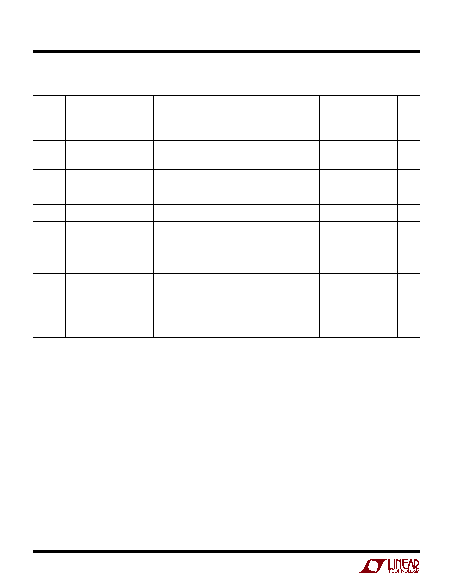
(LTC2054/LTC2055, LTC2054HV/LTC2055HV) The
q
denotes the
specifications which apply over the full operating temperature range, otherwise specifications are at T
A
= 25
∞
C. V
S
= 3V, 5V
unless otherwise noted. (Note 3)
ELECTRICAL CHARACTERISTICS
4
LTC2054/LTC2055
20545fa
SYMBOL
PARAMETER
CONDITIONS
MIN
TYP
MAX
MIN
TYP
MAX
UNITS
I
S
Supply Current
No Load (LTC2054)
q
175
210
175
215
µ
A
I
S
Supply Current (Per Amplifier)
No Load (LTC2055)
q
150
180
150
185
µ
A
V
OS
Input Offset Voltage
(Note 2)
±
0.5
±
5
±
0.5
±
5
µ
V
V
OS
/
T
Average Input Offset Drift
(Note 2)
q
0.025
±
0.03
0.025
±
0.05
µ
V/
∞
C
Long-Term Offset Drift
50
50
nV/
mo
I
B
Input Bias Current (Note 4)
±
3
±
3
pA
q
±
150
±
3000
pA
I
OS
Input Offset Current (Note 4)
±
6
±
6
pA
q
±
300
±
700
pA
e
n
Input Noise Voltage
R
S
= 100
, DC to 1Hz
0.6
0.6
µ
V
P-P
R
S
= 100
, DC to 10Hz
1.6
1.6
µ
V
P-P
CMRR
Common Mode Rejection Ratio
V
CM
= GND to V
+
≠ 0.9
120
130
120
130
dB
q
115
115
dB
PSRR
Power Supply Rejection Ratio
V
S
= 2.7V to 11V
120
130
120
130
dB
q
115
115
dB
AVOL
Large-Signal Voltage Gain
R
L
= 100k, V
OUT
= GND
125
140
125
140
dB
q
120
120
dB
V
OUT
Maximum Output Voltage Swing
R
L
= 5k to GND
±
4.78
±
4.82
±
4.78
±
4.82
V
R
L
= 5k to GND
q
±
4.75
±
4.70
V
R
L
= 100k to GND
±
4.98
±
4.99
±
4.98
±
4.99
V
R
L
= 100k to GND
q
±
4.975
±
4.97
V
SR
Slew Rate
0.5
0.5
V/
µ
s
GBW
Gain Bandwidth Product
500
500
kHz
f
S
Internal Sampling Frequency
1
1
kHz
(LTC2054HV/LTC2055HV) The
q
denotes the specifications which apply
over the full operating temperature range, otherwise specifications are at T
A
= 25
∞
C. V
S
=
±
5V
unless otherwise noted. (Note 3)
ELECTRICAL CHARACTERISTICS
Note 1: Absolute Maximum Ratings are those values beyond which the life
of the device may be impaired.
Note 2: These parameters are guaranteed by design. Thermocouple effects
preclude measurements of these voltage levels during automated testing.
Note 3: All versions of the LTC2054/LTC2055 are designed, characterized
and expected to meet the extended temperature limits of ≠ 40
∞
C and
125
∞
C. The LTC2054C/LTC2055C/LTC2054HVC/LTC2055HVC are
guaranteed to meet the temperature limits of 0
∞
C and 70
∞
C. The LTC2054I/
LTC2055I/LTC2054HVI/LTC2055HVI are guaranteed to meet temperature
limits of ≠ 40
∞
C and 85
∞
C. The LTC2054H/LTC2055HVH and LTC2054H/
LTC2055HVH are guaranteed to meet the temperature limits of ≠ 40
∞
C and
125
∞
C.
Note 4: Limit is determined by high speed automated test capability. See
Typical Chacteristic curves for actual typical performance. For tighter
specifications, please consult Linear Technology Marketing.
Note 5: The
JA
specified for the DD package is with minimal PCB heat
spreading metal. Using expanded metal area on all layers of a board
reduces this value.
LTC2054HVC/LTC2055HVC
LTC2054HVI/LTC2055HVI LTC2054HVH/LTC2055HVH

5
LTC2054/LTC2055
20545fa
Output Voltage Swing
vs Load Resistance
Common Mode Rejection Ratio
vs Frequency
DC CMRR
vs Common Mode Input Range
PSRR vs Frequency
TYPICAL PERFOR A CE CHARACTERISTICS
U
W
Input Bias Current vs Input
Common Mode Voltage
Output Swing
vs Load Current
Gain/Phase vs Frequency
FREQUENCY (Hz)
20
CMRR (dB)
40
80
120
140
1
100
1k
100k
20545 G01
0
10
10k
60
100
V
S
= 3V OR 5V
V
CM
= 0.5V
P-P
V
CM
(V)
20
CMRR (dB)
40
80
120
140
1
3
4
0
20545 G02
0
2
5
60
100
V
S
= 3V
V
S
= 5V
T
A
= 25
∞
C
FREQUENCY (Hz)
10
PSRR (dB)
140
120
100
80
60
40
20
0
≠20
≠40
100
1k
10k
100k
20545 G03
1M
+PSRR
V
S
=
±
2.5V
≠PSRR
LOAD RESISTANCE (k
)
0
OUTPUT SWING (V)
2
4
20545 G04
6
5
4
3
2
1
0
≠1
≠ 2
≠ 3
≠ 4
≠ 5
R
L
TO GND
V
S
=
±
5V
V
S
=
±
2.5V
V
S
=
±
2.5V
V
S
=
±
1.5V
V
S
=
±
1.5V
V
S
=
±
5V
10
100
1k
10k
100k
1M
10M
FREQUENCY (Hz)
GAIN (dB)
20
40
60
120
100
20545 G07
≠20
≠40
80
≠160
≠140
≠120
≠60
≠80
≠200
0
≠180
≠220
≠100
PHASE (DEG)
V
S
=
±
2.5V
V
IN
= 0.5V
P-P
R
L
= 10k
C
L
= 30pF
C
L
= 50pF
C
L
= 100pF
GAIN
PHASE
SOURCING OR SINKING LOAD CURRENT (mA)
0
V
+
V
+
≠ 0.5
V
+
≠ 1.0
V
+
≠ 1.5
V
≠ +
1.5
V
≠ +
1.0
V
≠ +
0.5
V
≠
3
20545 G06
1
2
4
5
OUTPUT SWING (V)
V
S
=
±
2.5V
V
S
=
±
2.5V
V
S
=
±
5V
V
S
=
±
5V
V
S
=
±
1.5V
V
S
=
±
1.5V
Input Bias Current vs
Temperature
TEMPERATURE (
∞
C)
≠40
BIAS CURRENT (pA)
125
20545 G08
25
45
70
85
10000
1000
100
10
1
0.1
5
≠15
V
S
= 3V
V
S
= 5V
V
S
= 10V
BIAS CURRENT (pA)
10000
1000
100
10
1
0.1
COMMON MODE VOLTAGE (V)
0
1.0
2.0 2.5
4.5
20545 G09
0.5
1.5
3.0 3.5 4.0
T
A
= ≠40
∞
C
T
A
= 70
∞
C
T
A
= 85
∞
C
T
A
= 125
∞
C
T
A
= 25
∞
C
V
SUPPLY
=
±
2.5V
Short-Circuit Output Current vs
Supply Voltage
TOTAL SUPPLY VOLTAGE, V
+
TO V
≠
(V)
3
4
5
≠6
≠8
≠10
SHORT-CIRCUIT OUTPUT CURRENT, I
OUT
(mA)
≠4
≠2
0
2
6
6
8
7
9
20545 G14
10
11
4
I
SINK
V
OUT
= V
+
I
SOURCE
V
OUT
= V
≠