4065fa.pm65
1
LTC4065/LTC4065A
4065fa
Wireless PDAs
Cellular Phones
Portable Electronics
Standalone 750mA Li-Ion
Battery Charger in 2
× 2 DFN
Complete Linear Charger in 2mm
××
××
× 2mm DFN
Package
C/10 Charge Current Detection Output
Timer Termination
Charge Current Programmable up to 750mA with
5% Accuracy
No External MOSFET, Sense Resistor or Blocking
Diode Required
Preset 4.2V Float Voltage with 0.6% Accuracy
Constant-Current/Constant-Voltage Operation with
Thermal Feedback to Maximize Charging Rate
Without Risk of Overheating
ACPR Pin Indicates Presence of Input Supply
(LTC4065A Only)
Charge Current Monitor Output for Gas Gauging
Automatic Recharge
Charges Single Cell Li-Ion Batteries Directly from
USB Port
20
µA Supply Current in Shutdown Mode
Soft-Start Limits Inrush Current
Tiny 6-Lead (2mm
× 2mm) DFN Package
FEATURES
DESCRIPTIO
U
APPLICATIO S
U
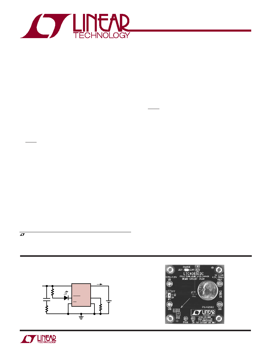
TYPICAL APPLICATIO
U
+
V
CC
R1
510
R2*
1
500mA
R3
2k
4065 TA01
4.2V
Li-Ion
BATTERY
V
IN
4.3V TO 5.5V
C1
1
µF
*SERIES 1
RESISTOR ONLY NEEDED FOR INDUCTIVE INPUT SUPPLIES
LTC4065
CHRG
EN
BAT
PROG
GND
The LTC
®
4065 is a complete constant-current/constant-
voltage linear charger for single-cell lithium-ion batteries.
Its 2mm
× 2mm DFN package and low external component
count make the LTC4065 especially well-suited for por-
table applications. Furthermore, LTC4065 is specifically
designed to work within USB power specifications.
The CHRG pin indicates when charge current has dropped
to ten percent of its programmed value (C/10). An internal
timer terminates charging according to battery manufac-
turer specifications.
No external sense resistor or blocking diode is required
due to the internal MOSFET architecture. Thermal feed-
back regulates charge current to limit the die temperature
during high power operation or high ambient temperature
conditions.
When the input supply (wall adapter or USB supply) is
removed, the LTC4065 automatically enters a low current
state, dropping battery drain current to less than 1
µA. With
power applied, LTC4065 can be put into shutdown mode,
reducing the supply current to less than 20
µA.
The full-featured LTC4065 also includes automatic re-
charge, low-battery charge conditioning (trickle charg-
ing), soft-start (to limit inrush current) and an open-drain
status pin to indicate the presence of an adequate input
voltage (LTC4065A only).
The LTC4065 is available in a tiny 6-lead, low profile
(0.75mm) 2mm
× 2mm DFN package.
, LTC and LT are registered trademarks of Linear Technology Corporation.
All other trademarks are the property of their respective owners.
Standalone Li-Ion Battery Charger
2
LTC4065/LTC4065A
4065fa
SYMBOL
PARAMETER
CONDITIONS
MIN
TYP
MAX
UNITS
V
CC
V
CC
Supply Voltage
(Note 4)
3.75
5.5
V
I
CC
Quiescent V
CC
Supply Current
V
BAT
= 4.5V (Forces I
BAT
and I
PROG
= 0)
120
250
µA
I
CCMS
V
CC
Supply Current in Shutdown
V
EN
= 5V (LTC4065) or Float PROG (LTC4065A)
20
40
µA
I
CCUV
V
CC
Supply Current in Undervoltage
V
CC
< V
BAT
, V
CC
= 3.5V, V
BAT
= 4V
6
11
µA
Lockout
V
FLOAT
V
BAT
Regulated Output Voltage
I
BAT
= 2mA
4.175
4.2
4.225
V
I
BAT
= 2mA, 0
°C < T
A
< 85
°C
4.158
4.2
4.242
V
I
BAT
BAT Pin Current
R
PROG
= 10k (0.1%), Current Mode
88
100
112
mA
R
PROG
= 2k (0.1%), Current Mode
475
500
525
mA
I
BMS
Battery Drain Current in Shutdown
V
EN
= V
CC
(LTC4065),
1
0
1
µA
Mode
V
PROG
> V
MS,PROG
(LTC4065A)
I
BUV
Battery Drain Current in Undervoltage V
CC
= 3.5V, V
BAT
= 4V
0
1
4
µA
Lockout
V
UVLO
V
CC
Undervoltage Lockout Voltage
V
CC
Rising
3.4
3.6
3.8
V
V
CC
Falling
2.8
3.0
3.2
V
V
PROG
PROG Pin Voltage
R
PROG
= 2k, I
PROG
= 500
µA
0.98
1
1.02
V
R
PROG
= 10k, I
PROG
= 100
µA
0.98
1
1.02
V
V
ASD
Automatic Shutdown Threshold
(V
CC
V
BAT
), V
CC
Low to High
60
82
100
mV
Voltage
(V
CC
V
BAT
), V
CC
High to Low
15
32
45
mV
V
MSH
Manual Shutdown High Voltage
V
EN
Rising
1
V
(LTC4065)
V
MSL
Manual Shutdown Low Voltage
V
EN
Falling
0.6
V
(LTC4065)
R
EN
EN Pin Input Resistance
0.95
1.5
3.3
M
V
CC
t < 1ms and Duty Cycle < 1% ................. 0.3V to 7V
Steady State ........................................... 0.3V to 6V
BAT, CHRG ................................................. 0.3V to 6V
EN (LTC4065), ACPR (LTC4065A) .. 0.3V to V
CC
+ 0.3V
PROG .............................................. 0.3V to V
CC
+ 0.3V
BAT Short-Circuit Duration ........................... Continuous
BAT Pin Current ................................................. 800mA
PROG Pin Current ............................................... 800
µA
Junction Temperature (Note 6) ............................ 125
°C
Operating Temperature Range (Note 2) .. 40
°C to 85°C
Storage Temperature Range ................ 65
°C to 125°C
ABSOLUTE AXI U RATI GS
W
W
W
U
PACKAGE/ORDER I FOR ATIO
U
U
W
(Note 1)
The
denotes specifications which apply over the full operating temperature range, otherwise specifications are T
A
= 25
°C.
V
CC
= 5V, V
BAT
= 3.8V, V
EN
= 0V (LTC4065 only) unless otherwise specified. (Note 2)
ELECTRICAL CHARACTERISTICS
T
JMAX
= 125
°C,
JA
= 60
°C/W (NOTE 3)
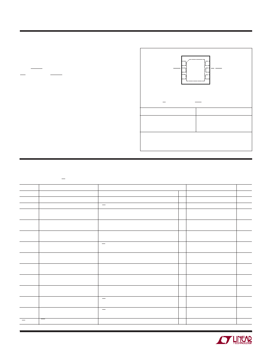
EXPOSED PAD (PIN 7) IS GND, MUST BE SOLDERED TO PCB
*EN PIN 5 ON LTC4065EDC, ACPR PIN 5 ON LTC4065AEDC
ORDER PART NUMBER
DC PART MARKING
Consult LTC Marketing for parts specified with wider operating temperature ranges.
LTC4065EDC
LTC4065AEDC
LBPG
LBVJ
Order Options Tape and Reel: Add #TR
Lead Free: Add #PBF Lead Free Tape and Reel: Add #TRPBF
Lead Free Part Marking:
http://www.linear.com/leadfree/
TOP VIEW
7
DC PACKAGE
6-LEAD (2mm
× 2mm) PLASTIC DFN
4
5
6
3
2
1
GND
CHRG
BAT
PROG
EN/ACPR*
V
CC
3
LTC4065/LTC4065A
4065fa
SYMBOL
PARAMETER
CONDITIONS
MIN
TYP
MAX
UNITS
I
PROG
PROG Pin Pull-Up Current
V
PROG
> 1V
3
µA
(LTC4065A)
V
MS,PROG
PROG Shutdown Threshold Voltage
V
PROG
Rising
3.7
4
4.3
V
(LTC4065A Only)
t
SS
Soft-Start Time
180
µs
I
TRKL
Trickle Charge Current
V
BAT
= 2V, R
PROG
= 2k (0.1%)
35
50
65
mA
V
TRKL
Trickle Charge Threshold Voltage
V
BAT
Rising
2.7
2.9
3.05
V
V
TRHYS
Trickle Charge Hysteresis Voltage
90
mV
V
RECHRG
Recharge Battery Threshold Voltage
V
FLOAT
V
RECHRG
, 0
°C < T
A
< 85
°C
70
100
130
mV
V
UVCL1
(V
CC
V
BAT
) Undervoltage Current
I
BAT
= 90% Programmed Charge Current
180
220
330
mV
V
UVCL2
Limit
I
BAT
= 10% Programmed Charge Current
90
125
150
mV
t
TIMER
Termination Timer
3
4.5
6
Hrs
Recharge Time
1.5
2.25
3
Hrs
Low-Battery Trickle Charge Time
V
BAT
= 2.5V
0.75
1.125
1.5
Hrs
V
ACPR
ACPR Pin Output Low Voltage
I
ACPR
= 5mA
60
105
mV
(LTC4065A)
I
ACPR
ACPR Pin Input Current (LTC4065A)
V
CC
= 4V, V
ACPR
= 4V, V
BAT
= 4.5V
0
1
µA
V
CHRG
CHRG Pin Output Low Voltage
I
CHRG
= 5mA
60
105
mV
I
CHRG
CHRG Pin Input Current
V
BAT
= 4.5V, V
CHRG
= 5V
0
1
µA
I
C/10
End of Charge Indication Current
R
PROG
= 2k (Note 5)
0.085
0.1
0.115
mA/mA
Level
T
LIM
Junction Temperature in Constant
115
°C
Temperature Mode
R
ON
Power FET "ON" Resistance
I
BAT
= 200mA
450
m
(Between V
CC
and BAT)
f
BADBAT
Defective Battery Detection CHRG
2
Hz
Pulse Frequency
D
BADBAT
Defective Battery Detection CHRG
80
%
Pulse Frequency Duty Ratio
The
denotes specifications which apply over the full operating temperature range, otherwise specifications are T
A
= 25
°C.
V
CC
= 5V, V
BAT
= 3.8V, V
EN
= 0V (LTC4065 only) unless otherwise specified. (Note 2)
ELECTRICAL CHARACTERISTICS
Note 1: Absolute Maximum Ratings are those values beyond which the life
of a device may be impaired.
Note 2: The LTC4065/LTC4065A are guaranteed to meet performance
specifications from 0
°C to 70°C. Specifications over the 40°C to 85°C
operating temperature range are assured by design, characterization and
correlation with statistical process controls.
Note 3: Failure to solder the exposed backside of the package to the PC
board ground plane will result in a thermal resistance much higher than
rated.
Note 4: Although the LTC4065 functions properly at 3.75V, full charge
current requires an input voltage greater than the desired final battery
voltage per the
V
UVCL1
specification.
Note 5: I
C/10
is expressed as a fraction of measured full charge current
with indicated PROG resistor.
Note 6: This IC includes overtemperature protection that is intended to
protect the device during momentary overload conditions. Junction
temperature will exceed 125
°C when overtemperature protection is active.
Continuous operation above the specified maximum operating junction
temperature may impair device reliability.
4
LTC4065/LTC4065A
4065fa
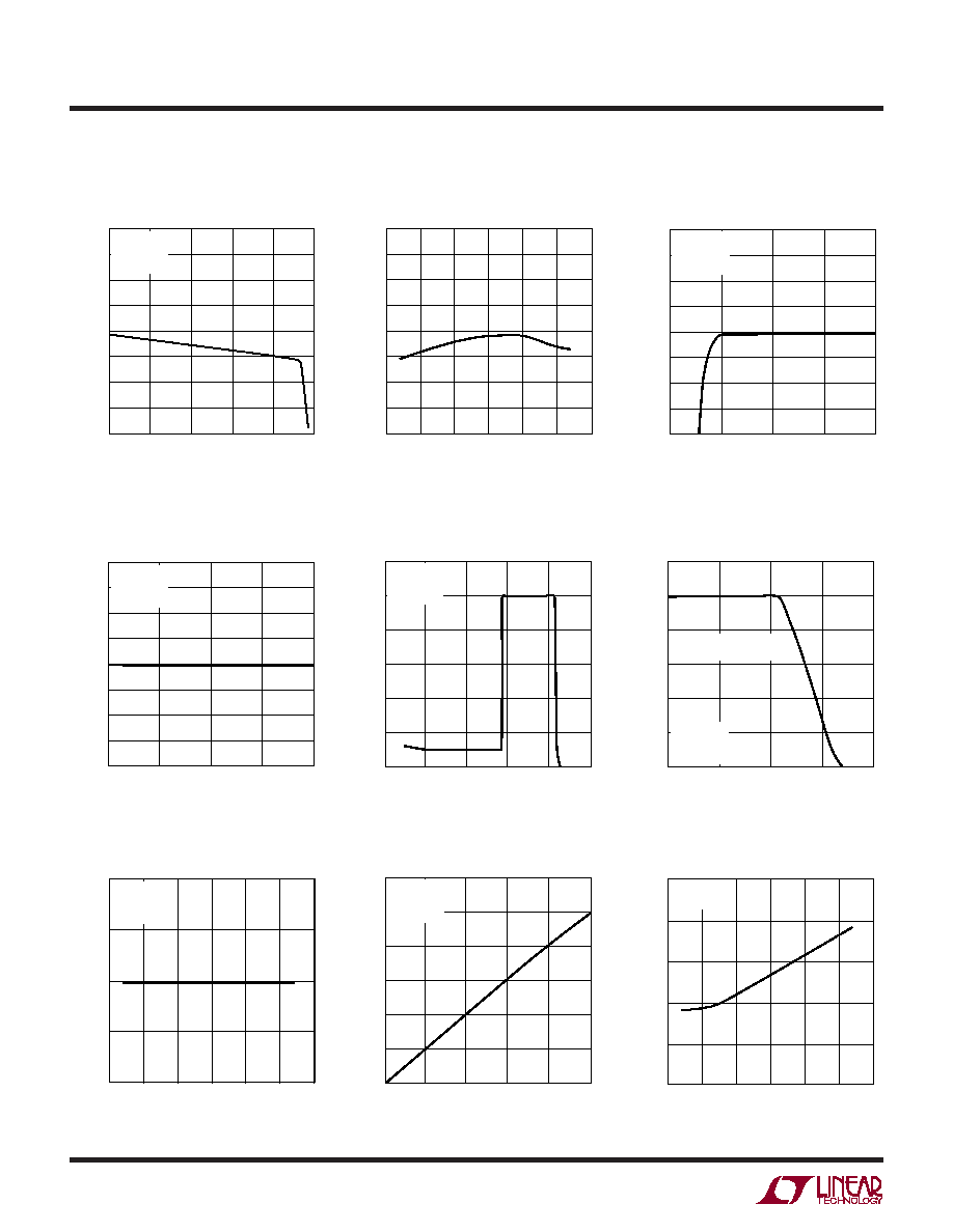
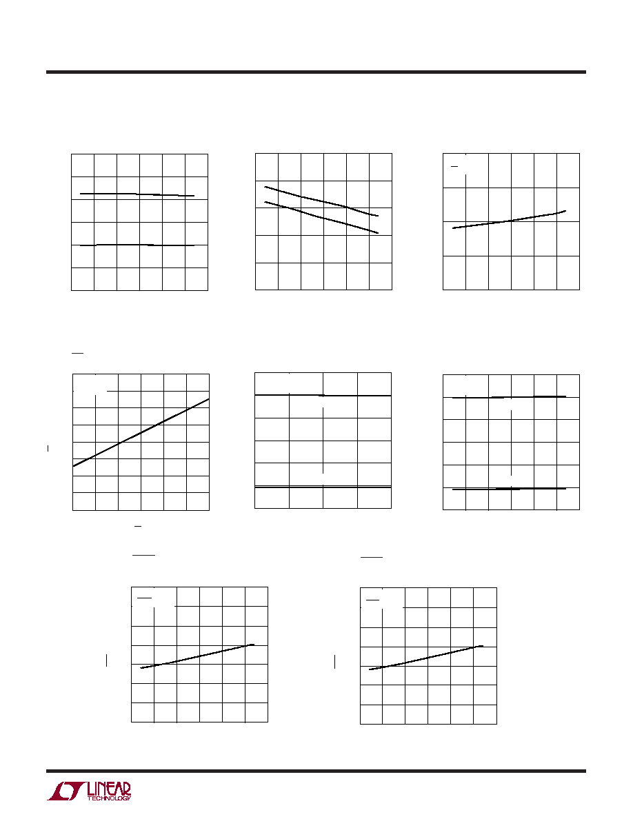
TYPICAL PERFOR A CE CHARACTERISTICS
U
W
Battery Regulation (Float) Voltage
vs Battery Charge Current
I
BAT
(mA)
0
V
FLOAT
(V)
4.19
4.20
4.21
300
500
4065 G01
4.18
4.17
4.16
100
200
400
4.22
4.23
4.24
V
CC
= 5V
T
A
= 25
°C
R
PROG
= 2k
TEMPERATURE (
°C)
50
V
FLOAT
(V)
4.23
25
4065 G02
4.20
4.18
25
0
50
4.17
4.16
4.24
4.22
4.21
4.19
75
100
SUPPLY VOLTAGE (V)
4
V
FLOAT
(V)
4.20
4.21
4.22
6
4065 G03
4.19
4.18
4.16
4.5
5
5.5
4.17
4.24
4.23
T
A
= 25
°C
I
BAT
= 2mA
R
PROG
= 2k
Battery Regulation (Float) Voltage
vs Temperature
Regulated Output (Float) Voltage
vs Supply Voltage
Charge Current vs Supply Voltage
(Constant Current Mode)
Charge Current vs Battery Voltage
Charge Current vs Temperature
with Thermal Regulation
(Constant Current Mode)
SUPPLY VOLTAGE (V)
4
0
I
BAT
(mA)
25
50
75
100
125
150
175
200
4.5
5
5.5
6
4065 G04
R
PROG
= 10k
V
BAT
= 3.8V
T
A
= 25
°C
V
BAT
(V)
0
0
I
BAT
(mA)
100
200
300
400
500
600
1
2
3
4
4065 G05
5
V
CC
= 5V
T
A
= 25
°C
R
PROG
= 2k
TEMPERATURE (
°C)
50
0
I
BAT
(mA)
100
200
300
400
0
50
100
150
4065 G06
500
600
THERMAL CONTROL
LOOP IN OPERATION
V
CC
= 5V
V
BAT
= 3.8V
R
PROG
= 2k
PROG Pin Voltage vs Temperature
(Constant Current Mode)
PROG Pin Voltage
vs Charge Current
Power FET On Resistance
vs Temperature
TEMPERATURE (
°C)
50
V
PROG
(V)
1.01
1.02
25
75
4065 G07
1.00
25
0
50
100
0.99
0.98
V
CC
= 5V
V
BAT
= 3.8V
R
PROG
= 10k
I
BAT
(mA)
0
0
V
PROG
(V)
0.2
0.4
0.6
0.8
1.0
1.2
100
200
300
400
4065 G08
500
V
CC
= 5V
T
A
= 25
°C
R
PROG
= 2k
TEMPERATURE (
°C)
50
300
R
DS
(m
)
350
400
450
500
550
25
0
25
50
4065 G09
75
100
V
CC
= 4V
I
BAT
= 400mA
5
LTC4065/LTC4065A
4065fa
TYPICAL PERFOR A CE CHARACTERISTICS
U
W
CHRG Pin Output Low Voltage
vs Temperature
Manual Shutdown Threshold
Voltage vs Temperature (LTC4065)
Manual Shutdown Supply Current
vs Temperature
TEMPERATURE (
°C)
50
80
100
140
25
75
4065 G10
60
40
25
0
50
100
20
0
120
V
CHRG
(mV)
V
CC
= 5V
I
CHRG
= 5mA
TEMPERATURE (
°C)
50
25
0.5
V
MS
(V)
0.7
1.0
0
50
75
4065 G11
0.6
0.9
0.8
25
100
FALL
RISE
TEMPERATURE (
°C)
50
0
I
CCMS
(
µ
A)
10
20
30
40
25
0
25
50
4065 G12
75
100
V
CC
= 5V
V
EN
= 5V
EN Pin Current (LTC4065)
Trickle Charge Current
vs Supply Voltage
V
EN
(V)
2
I
EN
(
µ
A)
1.5
2.0
2.5
3.5
4.5
4065 G13
1.0
0.5
0
2.5
3
4
3.0
3.5
4.0
5
V
CC
= 5V
T
A
= 25
°C
SUPPLY VOLTAGE (V)
4
0
I
BAT
(mA)
10
20
30
40
50
60
4.5
5
5.5
6
4065 G14
R
PROG
= 2k
R
PROG
= 10k
V
BAT
= 2V
T
A
= 25
°C
Trickle Charge Current
vs Temperature
TEMPERATURE (
°C)
50
I
BAT
(mA)
40
50
60
25
75
4065 G15
30
20
25
0
50
100
10
0
R
PROG
= 2k
R
PROG
= 10k
V
CC
= 5V
V
BAT
= 2V
ACPR Pin Output Low Voltage vs
Temperature (LTC4065A Only)
Undervoltage Lockout Threshold
Voltage vs Temperature
TEMPERATURE (
°C)
50
2.5
V
CC
(V)
2.8
3.0
3.3
3.5
4.0
25
0
25
RISE
FALL
50
4065 G16
75
100
3.8
TEMPERATURE (
°C)
50
80
100
140
25
75
4065 G17
60
40
25
0
50
100
20
0
120
V
ACPR
(mV)
V
CC
= 5V
I
ACPR
= 5mA