050912
WebSite
Europe
Tel: +49 2302 662-107
Americas
Tel: +1 404 699-7820
Asia
Tel: +852 26 14-1108
China
Tel: +86 21 6432 5146
www.wickmanngroup.com E-mail: sales@wickmann.com
E-mail: service@wickmannusa.com
E-mail: sales@wickmann.com.hk
E-mail: sales@wickmann.cn
1,65
2,8 ≠0,1
1,65
10 -0,5
cURus
Type (I) 100% x I
250% x I
500 mA ... 2.00 A > 4 h 1 ... 120 s
SS
SS
S
URFACE
URFACE
URFACE
URFACE
URFACE
M
M
M
M
M
OUNT
OUNT
OUNT
OUNT
OUNT
T
T
T
T
T
ELECOM
ELECOM
ELECOM
ELECOM
ELECOM
P
P
P
P
P
ROTECTORS
ROTECTORS
ROTECTORS
ROTECTORS
ROTECTORS
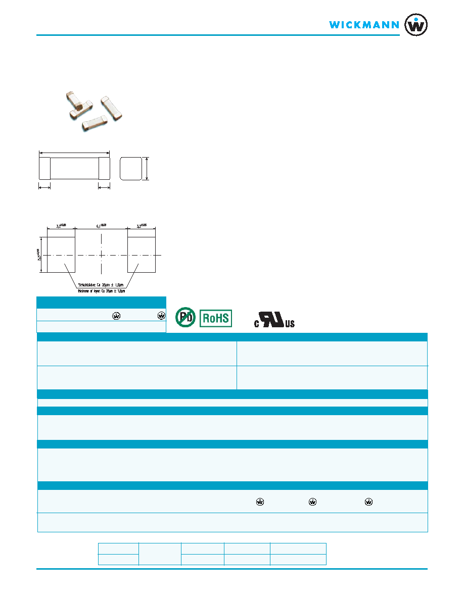
Dimensions (mm)
Dimensions (mm)
Dimensions (mm)
Dimensions (mm)
Dimensions (mm)
Operating Conditions
Operating Conditions
Operating Conditions
Operating Conditions
Operating Conditions
Order
Order
Order
Order
Order
Q t y .
Q t y .
Q t y .
Q t y .
Q t y .
Order-
Order-
Order-
Order-
Order-
Series
Series
Series
Series
Series
TT
TT
Type Code Packaging
ype Code Packaging
ype Code Packaging
ype Code Packaging
ype Code Packaging
Information
Information
Information
Information
Information
Number
Number
Number
Number
Number
457
TT
TT
Telecom T
elecom T
elecom T
elecom T
elecom Tube Protector
ube Protector
ube Protector
ube Protector
ube Protector
Overcurrent Protection for T
Overcurrent Protection for T
Overcurrent Protection for T
Overcurrent Protection for T
Overcurrent Protection for Telecom Equipment
elecom Equipment
elecom Equipment
elecom Equipment
elecom Equipment
TT
TT
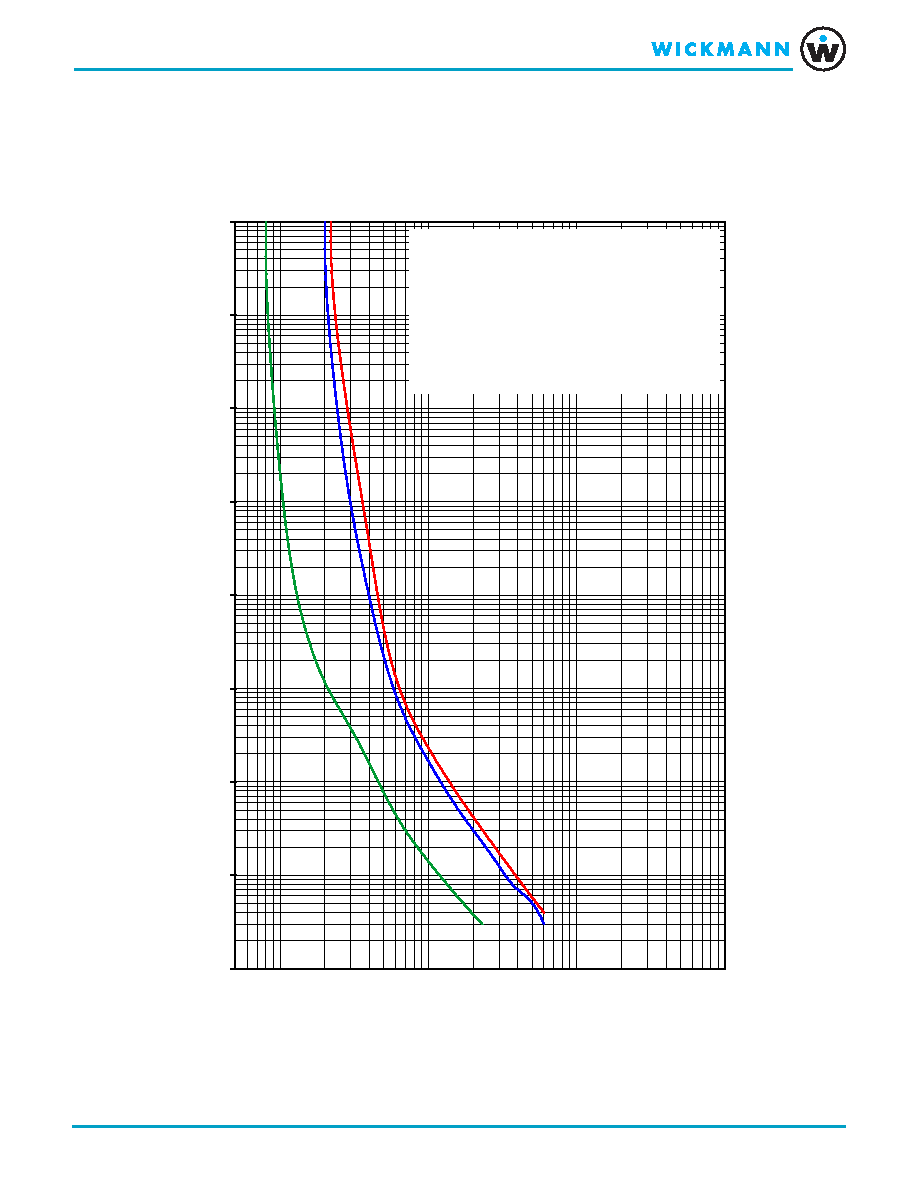
Time-Current Characteristic
ime-Current Characteristic
ime-Current Characteristic
ime-Current Characteristic
ime-Current Characteristic
Transient Tolerant
Applicable Standards
Applicable Standards
Applicable Standards
Applicable Standards
Applicable Standards
UL-248-14
UL 60950 3rd Edition *
Telcordia GR-1089 *
FCC 47 CFR Part 68
Approvals
Approvals
Approvals
Approvals
Approvals
cULus Recognized
Features
Features
Features
Features
Features
Surge proof for telecom line applications
No need for series resistors (1.25A & 2.00A)
Reduced PCB space requirements
Lead-free construction
Flame resistant ceramic housing
Irreversible physical separation under fault
Highly defined cut-off times
Low internal resistance minimizes line losses
For Reflow Soldering or Soldering Iron
W
W
W
W
WebLinks
ebLinks
ebLinks
ebLinks
ebLinks
Further info see:
Further info see:
Further info see:
Further info see:
Further info see:
www.wickmanngroup.com
Further application info see fuseology:
Further application info see fuseology:
Further application info see fuseology:
Further application info see fuseology:
Further application info see fuseology:
www.wickmanngroup.com/download/
fuseology.pdf
No.
No.
No.
No.
No. 457 Lead Free
457 Lead Free
457 Lead Free
457 Lead Free
457 Lead Free
Pad Layout
Pad Layout
Pad Layout
Pad Layout
Pad Layout
Chip Size 10030
Specifications
Specifications
Specifications
Specifications
Specifications
P a c k a g i n g
P a c k a g i n g
P a c k a g i n g
P a c k a g i n g
P a c k a g i n g
000: 2500 pcs./330mm reel (Blister Tape)
001: 500 pcs./178mm reel (Blister Tape)
Tape width 16mm
M a t e r i a l s
M a t e r i a l s
M a t e r i a l s
M a t e r i a l s
M a t e r i a l s
Housing:
Ceramic tube
Element:
Wire
Terminals: Copper, nickel & silver plated
Operating T
Operating T
Operating T
Operating T
Operating Temperature
emperature
emperature
emperature
emperature
-40 ∫C to +125 ∫C (consider de-rating)
Climatic T
Climatic T
Climatic T
Climatic T
Climatic Test
est
est
est
est
Damp heat, steady state
40 ∫C/ 93%/ 21 days (IEC 60068-1,-2-1,-2-2,-2-78)
Stock Conditions
Stock Conditions
Stock Conditions
Stock Conditions
Stock Conditions
+10 ∫C to +60 ∫C
relative humidity 75 % yearly average,
without dew, maximum value for 30 days - 95 %
Recommended soldering
Recommended soldering
Recommended soldering
Recommended soldering
Recommended soldering
240 ∫C, 30 s (Reflow)
S o l d e r a b i l i t y
S o l d e r a b i l i t y
S o l d e r a b i l i t y
S o l d e r a b i l i t y
S o l d e r a b i l i t y
acc. to IEC 60068-2-58
235 ∞C, 2 s
Soldering Heat Resistance
Soldering Heat Resistance
Soldering Heat Resistance
Soldering Heat Resistance
Soldering Heat Resistance
260 ∫C, 10 s (IEC 60068-2-58)
280 ∫C, 5 s (IEC 60068-2-58)
Minimum Cross Section, Copper
Minimum Cross Section, Copper
Minimum Cross Section, Copper
Minimum Cross Section, Copper
Minimum Cross Section, Copper
Conducting path - 0.175 mm
2
Path thickness - 0.035 mm
Mounting
Mounting
Mounting
Mounting
Mounting
Avoid circuit traces below the Fuse.
Fuse should not be enclosed in potting
materials.
M a r k i n g
M a r k i n g
M a r k i n g
M a r k i n g
M a r k i n g
Logo, Current Rating
Unit Weight
Unit Weight
Unit Weight
Unit Weight
Unit Weight
0.25 g (approx.)
Lightning Surge Specifications
Lightning Surge Specifications
Lightning Surge Specifications
Lightning Surge Specifications
Lightning Surge Specifications
Specifications are subject
to change without notice
Electrical Specifications
Electrical Specifications
Electrical Specifications
Electrical Specifications
Electrical Specifications
Surge Specification
Surge
Repetitions Waveform (
µ
sec.) Current (A)
Voltage (V)
Performance Requirement
FCC 47 Part 68
Logitudinal Type A
2
10x160
70A
1500
Fuse cannot open
FCC 47 Part 68
Metallic Type A
2
10x560
45A
800
Fuse cannot open
Telcordia GR-1089-CORE
First Level Lightning
50
10x1000
30A
1000
Fuse cannot open
FCC 47 Part 68
Longitudinal Type A
2
10x160
160
1500
Fuse cannot open
FCC 47 Part 68
Metallic Type A
2
10x560
115
800
Fuse cannot open
Telcordia GR-1089-CORE
First Level Lightning
50
10x1000
100
1.000
Fuse cannot open
Telcordia GR-1089-CORE
First Level Lighting
50
2x10
500
2.500
Fuse cannot open
0500 tested
0500 tested
0500 tested
0500 tested
0500 tested
1250 and 1251 tested
1250 and 1251 tested
1250 and 1251 tested
1250 and 1251 tested
1250 and 1251 tested
Type Code
Current
Voltage Rating
Interrupting Rating
Voltage Drop
Cold Resistance
Melting Integral
Approvals
AC
250VAC
600VAC
1.0 x I
N
0.1 x I
N
10 x I
N
50/60 Hz
cos=1
max. (mV)
max. (m
)
typ. (A
2
s)
0500
500mA
250V
50A
60A
450
640
2
∑
1250
1.25A
250V
50A
60A
250
150
16
∑
1251
2.00A
250V
50A
60A
375
115
18
∑
UL 60950 3rd Edition *
Telcordia1089 (2nd Level) *
Type
Test M1
Test M2
Test M3
Test M3
Test 1
Test 2
Test 3
Test 4
Code
600V/1.5s
600V/5s
600V/30min
Max. T (
∫
C)
277V/15min
600V/5s
600V/5s
600V/15min
AC Power Fault Ratings ∑
AC Power Fault Ratings ∑
AC Power Fault Ratings ∑
AC Power Fault Ratings ∑
AC Power Fault Ratings ∑ Permissible continuous operating current is
Permissible continuous operating current is
Permissible continuous operating current is
Permissible continuous operating current is
Permissible continuous operating current is 80
80
80
80
80 % at ambient
% at ambient
% at ambient
% at ambient
% at ambient temperature of 23
temperature of 23
temperature of 23
temperature of 23
temperature of 23 ∫C
∫C
∫C
∫C
∫C (73.4
(73.4
(73.4
(73.4
(73.4 ∫F)
∫F)
∫F)
∫F)
∫F)
0500
40A
7A
2.2A
--
25A
60A
7A
2.2A
1250
40A
7A
2.2A
120
25A
60A
7A
2.2A
1251
40A
7A
2.2A
50
25A
60A
7A
2.2A
* UL60950 3rd edition
* UL60950 3rd edition
* UL60950 3rd edition
* UL60950 3rd edition
* UL60950 3rd edition aaaaand T
nd T
nd T
nd T
nd Telcordia 1089 (2nd Level)
elcordia 1089 (2nd Level)
elcordia 1089 (2nd Level)
elcordia 1089 (2nd Level)
elcordia 1089 (2nd Level) are device standards, which require a testing of the complete device.
are device standards, which require a testing of the complete device.
are device standards, which require a testing of the complete device.
are device standards, which require a testing of the complete device.
are device standards, which require a testing of the complete device.
This product is not recommended
for new designs. Please refer to
Littelfuse No. 461.