Silicon Avalanche Diodes
6
w w w . l i t t e l f u s e . c o m
P6SMBJ Series
600W Surface Mount Transient Voltage Supressors
Agency Approvals: Recognized under the Components Program
of Underwriters Laboratories.
Agency File Number: E128662
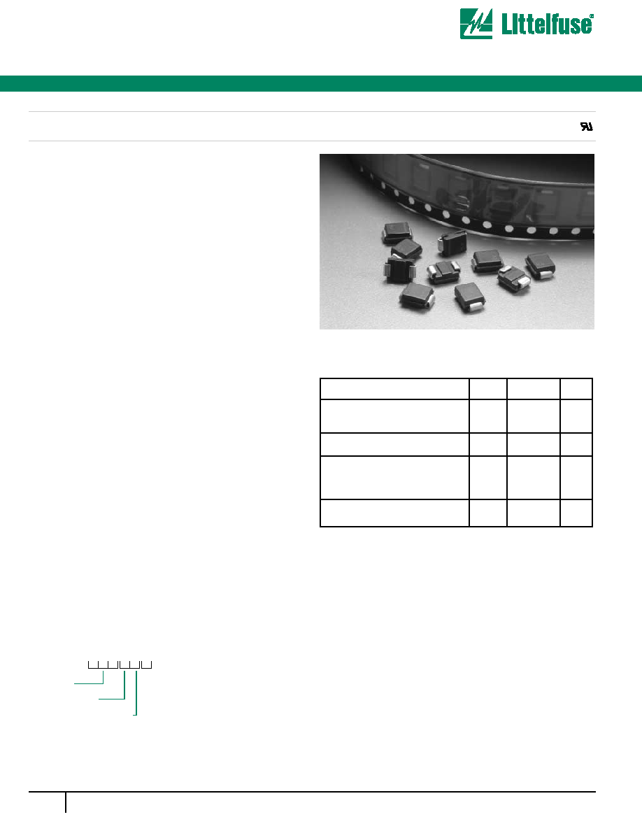
ORDERING INFORMATION
P6SMBJ
C A
Voltage
Bi-Directional
5% Voltage Tolerance
FEATURES
·
For surface mounted applications in order to optimize
board space
·
Low profile package
·
Built-in strain relief
·
Glass passivated junction
·
Low inductance
·
Excellent clamping capability
·
Repetition Rate (duty cycle): 0.01%
·
Fast response time: typically less than 1.0ps from 0 Volts to
BV for unidirectional types
·
Typical IR less than 1 mA above 10V
·
High Temperature soldering: 250°C/10 seconds at terminals
·
Plastic packages has Underwriters Laboratory
Flammability 94V-O
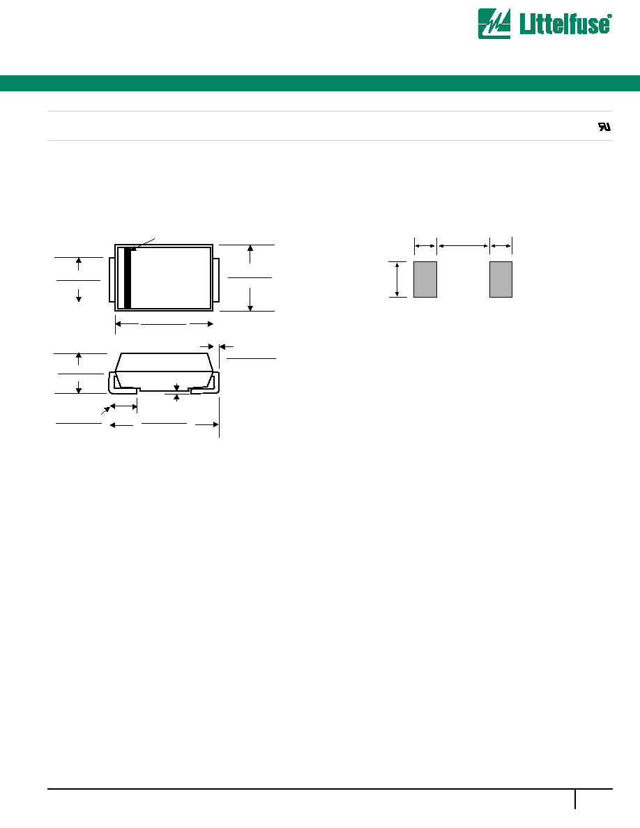
MECHANICAL CHARACTERISTICS
·
Case:JEDEC DO214AA. Molded plastic over glass passivated
junction
·
Terminal: Solder plated, solderable per MIL-STD-750
Method 2026
·
Polarity. Color band denotes positive end(cathode) except
Bidirectional
·
Standard Packaging: 12mm tape(EIA STF RS-481)
·
Weight: 0.003 ounce, 0.093 gram
DEVICES FOR BIPOLAR APPLICATIONS
For Bidirectional use C or CA Suffix for types SMBJ5.0 thru types
SMBJ110(e.g. SMBJ5.OC, SMBJ170CA)
Electrical characteristics apply in both directions
MAXIMUM RATINGS @25°C AMBIENT TEMPERATURE
AND CHARACTERISTICS (unless otherwise noted)
PARAMETER
Peak pulse power Dissipation on
10/1000µs waveform
(note 1,2, FIG.1)
Peak pulse current of on 10\1000µs
waveform (note 1, FIG.3)
Peak forward Surge Current, 8.3ms
Single Half SIne Wave Superimposed
on Rated Load, (JEDEC Method)
(note 2.3)
Operating junction and Storage
Temperature Range
VALUE
Min
600
SEE TABLE 1
100
-55 to +150
-55 to +150
UNIT
Watts
Amps
Amps
°C
Note 1. Non-repetitive current pulse, per Fig.3 and derated above
TA= 25°C per Fig.2
Note 2. Mounted on 5.0mm2(0.03mm thick) Copper Pads to each
terminal
Note 3. 8.3 ms single half sine-wave, or equivalent square wave,
Duty cycle= 4 pulses per minute
SYMBOL
PPPM
IPPM
IPSM
Tj, TsTG
®
P6SMBJ Series
Silicon Avalanche Diodes
600W Surface Mount Transient Voltage Supressors
7
w w w . l i t t e l f u s e . c o m
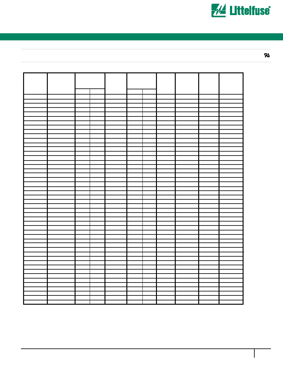
Part
Number
(Uni)
Part
Number
(Bi)
Device Marking
Code
Breakdown
Voltage
V
BR
(Volts) @ I
T
Maximum
Reverse
Leakage
I
R
@ V
R
(µA)
Maximum
Clamping
Voltage
V
C
@ I
PP
(Volts)
Maximum
Peak Pulse
Current
I
PP
(A)
ELECTRICAL SPECIFICATION @ Tamb 25°C
P6SMBJ 6.8A
P6SMBJ 6.8CA
6V8A
6V8C
5.80
6.45
7.14
10
10.5
58.1
1000
P6SMBJ 7.5A
P6SMBJ 7.5CA
7V5A
7V5C
6.40
7.13
7.88
10
11.3
54.0
500
P6SMBJ 8.2A
P6SMBJ 8.2CA
8V2A
8V2C
7.02
7.79
8.61
10
12.1
50.4
200
P6SMBJ 9.1A
P6SMBJ 9.1CA
9V1A
9V1C
7.78
8.65
9.55
1
13.4
45.5
50
P6SMBJ 10A
P6SMBJ 10CA
10A
10C
8.55
9.50
10.50
1
14.5
42.1
10
P6SMBJ 11A
P6SMBJ 11CA
11A
11C
9.40
10.50
11.60
1
15.6
39.1
5
P6SMBJ 12A
P6SMBJ 12CA
12A
12C
10.20
11.40
12.60
1
16.7
36.5
5
P6SMBJ 13A
P6SMBJ13CA
13A
13C
11.10
12.40
13.70
1
18.2
33.5
5
P6SMBJ 15A
P6SMBJ 15CA
15A
15C
12.80
14.30
15.80
1
21.2
28.8
5
P6SMBJ 16A
P6SMBJ 16CA
16A
16C
13.60
15.20
16.80
1
22.5
27.1
5
P6SMBJ 18A
P6SMBJ 18CA
18A
18C
15.30
17.10
18.90
1
25.5
24.2
5
P6SMBJ 20A
P6SMBJ 20CA
20A
20C
17.10
19.00
21.00
1
27.7
22.0
5
P6SMBJ 22A
P6SMBJ 22CA
22A
22C
18.80
20.90
23.10
1
30.6
19.9
5
P6SMBJ 24A
P6SMBJ 24CA
24A
24C
20.50
22.80
25.20
1
33.2
18.4
5
P6SMBJ 27A
P6SMBJ 27CA
27A
27C
23.10
25.70
28.40
1
37.5
16.3
5
P6SMBJ 30A
P6SMBJ 30CA
30A
30C
25.60
28.50
31.50
1
41.4
14.7
5
P6SMBJ 33A
P6SMBJ 33CA
33A
33C
28.20
31.40
34.70
1
45.7
13.3
5
P6SMBJ 36A
P6SMBJ 36CA
36A
36C
30.80
34.20
37.80
1
49.9
12.2
5
P6SMBJ 39A
P6SMBJ 39CA
39A
39C
33.30
37.10
41.00
1
53.9
11.3
5
P6SMBJ43A
P6SMBJ 43CA
43A
43C
36.80
40.90
45.20
1
59.3
10.3
5
P6SMBJ 47A
P6SMBJ 47CA
47A
47C
40.20
44.70
49.40
1
64.8
9.4
5
P6SMBJ 51A
P6SMBJ 51CA
51A
51C
43.60
48.50
53.60
1
70.1
8.7
5
P6SMBJ 56A
P6SMBJ 56CA
56A
56C
47.80
53.20
58.80
1
77.0
7.9
5
P6SMBJ 62A
P6SMBJ 62CA
62A
62C
53.00
58.90
65.10
1
85.0
7.2
5
P6SMBJ 68A
P6SMBJ 68CA
68A
68C
58.10
64.60
71.40
1
92.0
6.6
5
P6SMBJ 75A
P6SMBJ 75CA
75A
75C
64.10
71.30
78.80
1
103.0
5.9
5
P6SMBJ 82A
P6SMBJ 82CA
82A
82C
70.10
77.90
86.10
1
113.0
5.4
5
P6SMBJ 91A
P6SMBJ 91CA
91A
91C
77.80
86.50
95.50
1
125.0
4.9
5
P6SMBJ 100A
P6SMBJ 100CA
100A
100C
85.50
95.00
105.00
1
137.0
4.5
5
P6SMBJ 110A
P6SMBJ 110CA
110A
110C
94.00
105.00
116.00
1
152.0
4.0
5
P6SMBJ 120A
P6SMBJ 120CA
120A
120C
102.00
114.00
126.00
1
165.0
3.7
5
P6SMBJ 130A
P6SMBJ 130CA
130A
130C
111.00
124.00
137.00
1
179.0
3.4
5
P6SMBJ 150A
P6SMBJ 150CA
150A
150C
128.00
143.00
158.00
1
207.0
2.9
5
P6SMBJ 160A
P6SMBJ 160CA
160A
160C
136.00
152.00
168.00
1
219.0
2.8
5
P6SMBJ 170A
P6SMBJ 170CA
170A
170C
145.00
162.00
179.00
1
234.0
2.6
5
P6SMBJ 180A
P6SMBJ 180CA
180A
180C
154.00
171.00
189.00
1
246.0
2.5
5
P6SMBJ 200A
P6SMBJ 200CA
200A
200C
171.00
190.00
210.00
1
274.0
2.2
5
P6SMBJ 220A
P6SMBJ 220CA
220A
220C
185.00
209.00
231.00
1
328.0
1.9
5
P6SMBJ 250A
P6SMBJ 250CA
250A
250C
214.00
237.00
263.00
1
344.0
1.8
5
P6SMBJ 300A
P6SMBJ 300CA
300A
300C
256.00
285.00
315.00
1
414.0
1.5
5
P6SMBJ 350A
P6SMBJ 350CA
350A
350C
300.00
332.00
368.00
1
482.0
1.3
5
P6SMBJ 400A
P6SMBJ 400CA
400A
400C
342.00
380.00
420.00
1
548.0
1.1
5
P6SMBJ 440A
P6SMBJ 440CA
440A
440C
376.00
418.00
462.00
1
602.0
1.0
5
P6SMBJ 480A
P6SMBJ 480CA
480A
480C
408.00
456.00
504.00
1
658.0
0.9
5
P6SMBJ 510A
P6SMBJ 510CA
510A
510C
434.00
485.00
535.00
1
698.0
0.9
5
P6SMBJ 530A
P6SMBJ 530CA
530A
530C
477.00
503.50
556.50
1
725.0
0.8
5
P6SMBJ 540A
P6SMBJ 540CA
540A
540C
459.00
513.00
567.00
1
740.0
0.8
5
P6SMBJ 550A
P6SMBJ 550CA
550A
550C
495.00
522.50
577.50
1
760.0
0.8
5
Reverse
Stand off
Voltage
V
R
(Volts)
UNI
BI
MIN
MAX
For bidirectional type having Vrwm of 10 volts and less, the IR limit is double.
The available parts are "A" type only, the parts without A (VBR is ± 10%) is not available.
Test
Current
I
T
(mA)
®
600W Surface Mount Transient Voltage Supressors
P6SMBJ Series
Silicon Avalanche Diodes
8
w w w . l i t t e l f u s e . c o m
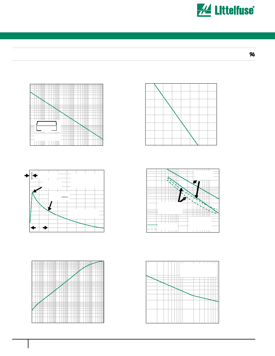
Ratings and Characteristic Curves TA=25°C unless otherwise noted
Fig. 1 Peak Pulse Power Rating
Fig. 3 Pulse Waveform
Fig. 5- Typ. Transient Thermal Impedance
Fig. 6- Maximum Non-Repetitive Peak
Fig. 4- Typical Junction Capacitance
Fig. 2 Pulse Derating Curve
td- Pulse Width (sec.)
TA- Ambient Temperature (°C)
P
PPM
- Peak Pulse Power (KW)
I PPM
- Peak Pulse Current, % I
RSM
Transient Thermal Impedance
(°C/W)
I PSM
-Peak Forward Surge Current (A)
C
J
-Junction Capacitance (pF)
Peak Pulse Power (P
PP
) or Current (I
PP
)
Derating in Percentage, %
0.1
µs
1.0
µs
10
µs
100
µs 1.0ms
10ms
0.1
1
10
100
0.2x0.2"(5.0x5.0mm)
Copper Pad Areas
0
0
0
0.1
1.0
10
100
50
100
150
1.0
2.0
3.0
4.0
0.001
0.01
0.1
1
10
100
1000
1
10
100
200
6000
1000
100
10
1.0
10
100
200
10
100
0
25
25
50
50
75
75
100
100
125 150 175 200
tp- Pulse Duration(sec)
Number of Cycles at 60Hz
VWM-Reverse Stand-Off Voltage (V)
Forward Surge Current
tr=10µsec
Peak Value
IPPM
Half Value IPPM
2
TJ=25°C
Pulse Width(td) is defined
as the point where the peak
current decays to 50% of IPPM
10/1000
µsec. Waveform
as defined by R.E.A
td
8.3 Single Half Sine-Wave
(JEDEC Method)
Undirectional Only
Measured at
Zero Bias
Uni-Directional
Bi-Directional
TJ=25°C
f=1.0MHZ
Vsig=50mVp-p
VR, Measured at
Stand-Off
Voltage, VWM
®