 | –≠–ª–µ–∫—Ç—Ä–æ–Ω–Ω—ã–π –∫–æ–º–ø–æ–Ω–µ–Ω—Ç: V131HB34 | –°–∫–∞—á–∞—Ç—å:  PDF PDF  ZIP ZIP |

2
V
ARIST
OR
PR
ODUCTS
Varistor Products
85
w w w . l i t t e l f u s e . c o m
High Energy Industrial
HB34 Varistor Series
The HB34 Series of transient surge suppressors are industrial high-
energy Metal-Oxide Varistors (MOVs). They are designed to provide
surge suppression in the AC mains outdoor and service entrance
environment (distribution panels) of buildings. HB34 applications also
include industrial heavy motors, controls, and power supplies such as
used in the oil-drilling, mining, and transportation fields, including HVAC
and motor/generator applications.
The HB34 Series provides rigid terminals for through-hole solder
mounting on printed circuit boards, thereby eliminating the need for
screw mounting.
See Ratings and Specifications table for part numbers.
Features
∑ Wide Operating Voltage Range
VM(AC)RMS. . . . . . . . . . . . . . . . . . . . . . . . . . . . . . . . . . . 130V to 750V
∑ High Energy Absorption
Capability. . . . . . . . . . . . . . . . . . . . . . . . . . . . . . .WTM = 200J to 1050J
∑ High Peak Pulse Current
Capability . . . . . . . . . . . . . . . . . . . . . . . . . . . . . . . . ITM = 40,000A
∑ Rigid Terminals for Secure Through-Hole Solder Mounting
∑ No Derating Up to 85
o
C Ambient
AGENCY APPROVALS:
Recognized under the components program of
Underwriters Laboratories. Certified by CSA.
AGENCY FILE NUMBERS:
UL E75961, CSA LR91788.
Æ
Æ
Next
Previous

High Energy Industrial
HB34 Varistor Series
Varistor Products
86
w w w . l i t t e l f u s e . c o m
Absolute Maximum Ratings
For ratings of individual members of a series, see Device Ratings and Specifications chart
Continuous:
Steady State Applied Voltage:
AC Voltage Range (VM(AC)RMS) . . . . . . . . . . . . . . . . . . . . . . . . . . . . . . . . . . . . . . . . . . . . . . . . . . . . . . . . . . . . . . . . . . 130 to 750
V
DC Voltage Range (VM(DC)). . . . . . . . . . . . . . . . . . . . . . . . . . . . . . . . . . . . . . . . . . . . . . . . . . . . . . . . . . . . . . . . . . . . . . 175 to 970
V
Transient:
Peak Pulse Current (ITM)
For 8/20µs Current Wave (See Figure 2) . . . . . . . . . . . . . . . . . . . . . . . . . . . . . . . . . . . . . . . . . . . . . . . . . . . . . . . . . . . . . . 40,000
A
Single Pulse Energy Range
For 2ms Current Square Wave (WTM) . . . . . . . . . . . . . . . . . . . . . . . . . . . . . . . . . . . . . . . . . . . . . . . . . . . . . . . . . . . . . . 270 to 1050
J
Operating Ambient Temperature Range (TA) . . . . . . . . . . . . . . . . . . . . . . . . . . . . . . . . . . . . . . . . . . . . . . . . . . . . . . . . . . . . . -55 to 85
O
C
Storage Temperature Range (TSTG) . . . . . . . . . . . . . . . . . . . . . . . . . . . . . . . . . . . . . . . . . . . . . . . . . . . . . . . . . . . . . . . . . . -55 to 125
O
C
Temperature Coefficient (
V) of Clamping Voltage (VC) at Specified Test Current . . . . . . . . . . . . . . . . . . . . . . . . . . . . . . . . . . <0.01
%/
O
C
CAUTION: Stresses above those listed in "Absolute Maximum Ratings" may cause permanent damage to the device. This is a stress only rating and operation of the device
at these or any other conditions above those indicated in the operational sections of this specification is not implied.
Device Ratings and Specifications
HB34 SERIES UNITS
MODEL
NUMBER
SIZE
MAXIMUM RATINGS (85
o
C)
SPECIFICATIONS (25
o
C)
CONTINUOUS
TRANSIENT
VARISTOR VOLTAGE
AT 1mA DC TEST
CURRENT
MAXIMUM
CLAMPING
VOLTAGE
(V
C
) AT 200A
(8/20
µs)
TYPICAL
CAPACI-
TANCE
V
RMS
V
DC
ENERGY
(2ms)
PEAK
CURRENT
(8/20
µs)
V
M(AC)
V
M(DC)
W
TM
I
TM
MIN
V
N(DC)
MAX
V
C
f = 1MHz
(mm)
(V)
(V)
(V)
(A)
(V)
(V)
(V)
(V)
(pF)
V131HB34
34
130
175
270
40,000
184
200
228
345
10,000
V151HB34 34
150
200
300
40,000
212
240
268
405
8,000
V251HB34
34
250
330
370
40,000
354
390
429
650
5,000
V271HB34
34
275
369
400
40,000
389
430
473
730
4,500
V321HB34
34
320
420
460
40,000
462
510
561
830
3,800
V421HB34
34
420
560
600
40,000
610
680
748
1,130
3,000
V481HB34
34
480
640
650
40,000
670
750
825
1,240
2,700
V511HB34
34
510
675
700
40,000
735
820
910
1,350
2,500
V571HB34
34
575
730
770
40,000
805
910
1000
1,480
2,200
V661HB34
34
660
850
900
40,000
940
1050
1160
1,720
2,000
V751HB34
34
750
970
1050
40,000
1080
1200
1320
2,000
1,800
NOTE: Average power dissipation of transients not to exceed 2.0W.
1. Peak current applies to applications rated up to 115 V . Peak current is 30kA for applications greater than 115V .
2. Peak current applies to applications rated up to 132V . Peak Current is 30kA for applications greater than 132V .
RMS
RMS
1
RMS
RMS
2
Next
Previous

2
V
ARIST
OR
PR
ODUCTS
HB34 Varistor Series
Varistor Products
High Energy Industrial
87
w w w . l i t t e l f u s e . c o m
Power Dissipation Ratings
Should transients occur in rapid succession, the average power
dissipation result is simply the energy (watt-seconds) per pulse times the
number of pulses per second. The power so developed must be within
the specifications shown on the Device Ratings and Specifications table
for the specific device. The operating values must be derated as shown
in Figure 1.
Transient V-I Characteristics Curves
FIGURE 2. PEAK PULSE CURRENT TEST WAVEFORM
100
90
50
10
O
1
T
T
1
T
2
TIME
PERCENT OF PEAK V
ALUE
O
1
= Virtual Origin of Wave
T = Time From 10% to 90% of Peak
T
1
= Virtual Front time = 1.25 ∑ t
T
2
= Virtual Time to Half Value (Impulse Duration)
Example: For an 8/20
µs Current Waveform:
8
µs = T
1
= Virtual Front Time
20
µs = T
2
= Virtual Time to Half Value
FIGURE 3. CLAMPING VOLTAGE FOR V131HB34 - V751HB34
V
O
L
T
A
GE (V)
10000
1000
100
CURRENT (A)
V751HB34
V131HB34
V321HB34
V511HB34
V481HB34
V571HB34
V661HB34
TA = -55
oC TO 85oC
MAXIMUM CLAMPING VOLTAGE
VARISTOR SIZE 34mm
130 TO 750 VM(AC) RATING
V271HB34
V251HB34
V151HB34
V421HB34
-5
-4
1E-3
0.01
0.1
1
10
100
1,000
10,000
100,000
Next
Previous
High Energy Industrial
HB34 Varistor Series
Varistor Products
88
w w w . l i t t e l f u s e . c o m
Ordering Information
FIGURE 4. SURGE CURRENT RATING CURVES FOR
V131HB34 - V751HB34
DISC SIZE 34mm
V131HB34 - V751HB34
50,000
20,000
10,000
5,000
2,000
1,000
500
200
100
50
20
10
20
100
1,000
10,000
SURGE CURRENT (A)
IMPULSE DURATION (
µs)
10
1
INDEFINITE
10
5
10
2
2
10
3
10
4
10
6
NOTE: If pulse ratings are exceeded, a shift of VN(DC) (at specified current) of more than ±10% could result. This type of shift, which normally results in a decrease of VN(DC),
may result in the device not meeting the original published specifications, but it does not prevent the device from continuing to function, and to provide ample protection.
Pulse Rating Curves
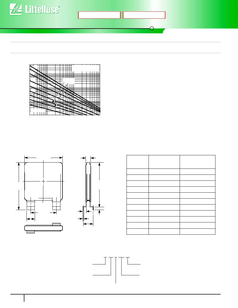
Mechanical Dimensions
NOTE: Dimension in mm is typical, unless otherwise specified.
37.0 MAX
49.5
MAX
22.0
±1.0
6.0
±0.1
0.55
S
44.5
MAX
2.5 TO
5.0
T
±0.1
2.30
±0.2
TABLE OF DIMENSIONS -
THICKNESS AND TERMINAL OFFSETS
PART TYPE
T
BODY THICKNESS
(MAXIMUM)
S
MOUNTING TERMINAL
OFFSET
V131HB34
5.7
5.50
±0.65
V151HB34
5.9
5.90
±0.65
V251HB34
6.1
6.25
±0.65
V271HB34
6.4
6.50
±0.65
V321HB34
6.9
6.90
±0.65
V421HB34
7.8
7.85
±0.85
V481HB34
8.3
8.25
±1.00
V511HB34
8.8
8.60
±1.00
V571HB34
9.4
8.85
±1.5
V661HB34
10.2
9.65
±1.5
V751HB34
10.7
10.65
±1.5
VARISTOR DESIGNATOR
MAX AC
RMS
WORKING VOLTAGE
(FIRST SIGNIFICANT DIGITS) V
M(AC)
DISC SIZE (mm)
SERIES DESIGNATOR
V
M(AC)
VOLTAGE DECADE MULTIPLIER
V 25 1 HB 34
Next
Previous