 | –≠–ª–µ–∫—Ç—Ä–æ–Ω–Ω—ã–π –∫–æ–º–ø–æ–Ω–µ–Ω—Ç: V131NA34 | –°–∫–∞—á–∞—Ç—å:  PDF PDF  ZIP ZIP |

122
w w w . l i t t e l f u s e . c o m
Varistor Products
High Energy Industrial Square Disc
NA Varistor Series
The NA Series of transient surge suppressors are varistors (MOVs) in
square disc form, intended for special industrial high-energy applications
requiring unique electrical contact or packaging methods provided by the
customer. The electrode finish of these devices is solderable and can
also be used with pressure contacts. Discs may also be stacked.
The NA Series varistor is a square 34mm device, with thicknesses
ranging from 1.7mm minimum for the 250V device to 7.5mm maximum
for the 750V device. For information on mounting considerations refer to
Application Note AN8820.
This disc is also available with encapsulation and PCB leads. See
Littelfuse HB34 Sales.
Features
∑ Provided in Disc Form for Unique Packaging by Customer
∑ Solderable Electrode Finish.
∑ Pressure Contacts and/or Disc Stacking may be Utilized
∑ Wide Operating Voltage Range
VM(AC)RMS . . . . . . . . . . . . . . . . . . . . . . . . . . . . . . . . . . .250V to 750V
∑ Peak Pulse Current Capability (ITM). . . . . . . . . . . . . . . . . . . .40,000A
∑ High Energy Capability (WTM). . . . . . . . . . . . . . . . . . . .370J to 1050J
∑ No Derating Up to 8
o
C Ambient
ALSO SEE HB34 SERIES

123
w w w . l i t t e l f u s e . c o m
Varistor Products
2
V
ARIST
OR
PR
ODUCTS
High Energy Industrial Square Disc
NA Varistor Series
Absolute Maximum Ratings
For ratings of individual members of a series, see Device Ratings and Specifications chart
Continuous:
Steady State Applied Voltage:
AC Voltage Range (VM(AC)RMS) . . . . . . . . . . . . . . . . . . . . . . . . . . . . . . . . . . . . . . . . . . . . . . . . . . . . . . . . . . . . . . . . . . . . . . . . . . 250 to 750
V
DC Voltage Range (VM(DC)). . . . . . . . . . . . . . . . . . . . . . . . . . . . . . . . . . . . . . . . . . . . . . . . . . . . . . . . . . . . . . . . . . . . . . . . . . . . . . 330 to 970
V
Transient:
Peak Pulse Current (ITM)
For 8/20µs Current Wave (See Figure 2) . . . . . . . . . . . . . . . . . . . . . . . . . . . . . . . . . . . . . . . . . . . . . . . . . . . . . . . . . . . . . . . . . . . . . . 40,000
A
Single Pulse Energy Range
For 2ms Current Square Wave (WTM) . . . . . . . . . . . . . . . . . . . . . . . . . . . . . . . . . . . . . . . . . . . . . . . . . . . . . . . . . . . . . . . . . . . . . . 370 to1050
J
Operating Ambient Temperature Range (TA) . . . . . . . . . . . . . . . . . . . . . . . . . . . . . . . . . . . . . . . . . . . . . . . . . . . . . . . . . . . . . . . . . . -55 to 85
O
C
Storage Temperature Range (TSTG) . . . . . . . . . . . . . . . . . . . . . . . . . . . . . . . . . . . . . . . . . . . . . . . . . . . . . . . . . . . . . . . . . . . . . . . . -55 to 125
O
C
Temperature Coefficient (
V) of Clamping Voltage (VC) at Specified Test Current . . . . . . . . . . . . . . . . . . . . . . . . . . . . . . . . . . . . . . <0.01
%/
O
C
CAUTION: Stresses above those listed in "Absolute Maximum Ratings" may cause permanent damage to the device. This is a stress only rating and operation of the
device at these or any other conditions above those indicated in the operational sections of this specification is not implied.
Device Ratings and Specifications
NA SERIES UNITS
MODEL
NUMBER
SIZE
MAXIMUM RATINGS (85
o
C)
SPECIFICATIONS (25
o
C)
CONTINUOUS
TRANSIENT
VARISTOR VOLTAGE
AT 1mA DC TEST
CURRENT
MAXIMUM
CLAMPING
VOLTAGE
(V
C
) AT 200A
(8/20
µ
s)
TYPICAL
CAPACI-
TANCE
V
RMS
V
DC
ENERGY
(2ms)
PEAK
CURRENT
(8/20
µ
s)
V
M(AC)
V
M(DC)
W
TM
I
TM
MIN
V
N(DC)
MAX
V
C
f = 1MHz
(mm)
(V)
(V)
(J)
(A)
(V)
(V)
(V)
(V)
(pF)
V131NA34
V141NA34
34
34
130
140
175
188
270
291
40,000
184
198
220
200
228
248
345
375
10,000
V151NA34
34
150
200
300
40,000
212
240
268
405
8,000
9,000
V251NA34
34
250
330
370
40,000
354
390
429
650
5,000
V271NA34
34
275
369
400
40,000
389
430
473
730
4,500
V321NA34
34
320
420
460
40,000
462
510
561
830
3,800
V421NA34
34
420
560
600
40,000
610
680
748
1,130
3,000
V481NA34
34
480
640
650
40,000
670
750
825
1,240
2,700
V511NA34
34
510
675
700
40,000
735
820
910
1,350
2,500
V571NA34
34
575
730
770
40,000
805
910
1000
1,480
2,200
V661NA34
34
660
850
900
40,000
940
1050
1160
1,720
2,000
V751NA34
34
750
970
1050
40,000
1080
1200
1320
2,000
1,800
NOTE: Average power dissipation of transients not to exceed 2.0W.
1
40,000
3
2
1. Peak current applies to applications rated up to 115V . Peak current is 30kA for applications greater than 115V .
2. Peak current applies to applications rated up to 132V . Peak current is 30kA for applications greater than 132V .
3. Peak current applies to applications rated up to 123V . Peak current is 30kA for applications greater than 123V .
RMS
RMS
RMS
RMS
RMS
RMS

124
w w w . l i t t e l f u s e . c o m
Varistor Products
NA Varistor Series
High Energy Industrial Square Disc
Power Dissipation Ratings
Should transients occur in rapid succession, the average power
dissipation required is simply the energy (watt-seconds) per pulse times
the number of pulses per second. The power so developed must be
within the specifications shown on the Device Ratings and Specifications
table for the specific device. The operating values must be derated as
shown in Figure 1.
Transient V-I Characteristics Curves
FIGURE 1. CURRENT, ENERGY AND POWER DERATING
CURVE
100
90
80
70
60
50
40
30
20
10
0
-55
50
60
70
80
90
100
110 120
130 140
150
PERCENT OF RA
TED
V
ALUE
AMBIENT TEMPERATURE (
o
C)
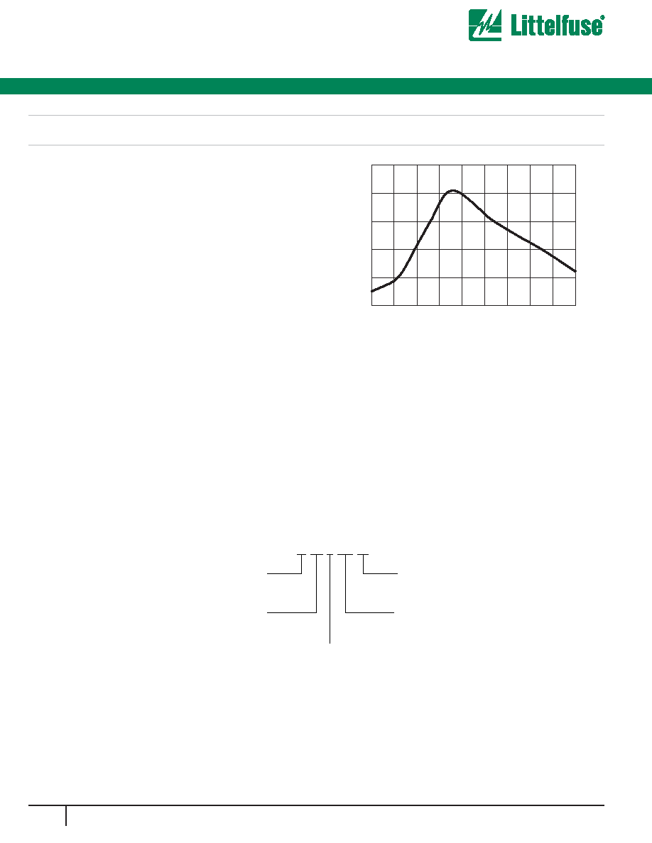
FIGURE 2. PEAK PULSE CURRENT TEST WAVEFORM
100
90
50
10
O
1
T
T
1
T
2
TIME
PERCENT OF PEAK V
ALUE
O
1
= Virtual Origin of Wave
T = Time From 10% to 90% of Peak
T
1
= Virtual Front time = 1.25 ∑ t
T
2
= Virtual Time to Half Value (Impulse Duration)
Example: For an 8/20
µ
s Current Waveform:
8
µ
s = T
1
= Virtual Front Time
20
µ
s = T
2
= Virtual Time to Half Value
FIGURE 3. CLAMPING VOLTAGE FOR V131NA34 - V751NA34
V
O
L
T
A
GE (V)
10000
1000
100
CURRENT (A)
V751NA34
V131NA34
V321NA34
V511NA34
V481NA34
V571NA34
V661NA34
T
A
= -55
o
C TO 85
o
C
MAXIMUM CLAMPING VOLTAGE
VARISTOR SIZE 34mm
130 TO 750 V
M(AC)
RATING
V271NA34
V251NA34
V151NA34
V421NA34
-5
-4
1E-3
0.01
0.1
1
10
100
1,000
10,000
100,000

125
w w w . l i t t e l f u s e . c o m
Varistor Products
2
V
ARIST
OR
PR
ODUCTS
High Energy Industrial Square Disc
NA Varistor Series
FIGURE 4. SURGE CURRENT RATING CURVES FOR
V131NA34 - V751NA34
DISC SIZE 34mm
V131NA34 - V751NA34
50,000
20,000
10,000
5,000
2,000
1,000
500
200
100
50
20
10
20
100
1,000
10,000
SURGE CURRENT (A)
IMPULSE DURATION (
µ
s)
10
1
INDEFINITE
10
5
10
2
2
10
3
10
4
10
6
Pulse Rating Curves
NOTE:If pulse ratings are exceeded, a shift of VN(DC) (at specified current) of more than ±10% could result. This type of shift, which normally results in a decrease of VN(DC),
may result in the device not meeting the original published specifications, but it does not prevent the device from continuing to function, and to provide ample protection.
Mechanical Dimensions
(MILLIMETERS)
MODEL
NUMBER
NA SERIES
VARISTOR THICKNESS
MILLIMETERS
INCHES
MIN
MAX
MIN
MAX
V131NA34
V141NA34
1.40
2.30
0.055
0.090
V151NA34
1.50
1.45
2.80
2.55
0.059
0.057
0.011
0.100
V251NA34
1.70
2.30
0.066
0.090
V271NA34
1.80
2.70
0.070
0.106
V321NA34
2.10
3.00
0.082
0.118
V421NA34
3.00
4.00
0.118
0.157
V481NA34
3.20
4.40
0.125
0.173
V511NA34
3.60
4.90
0.141
0.192
V571NA34
4.00
5.60
0.118
0.220
V661NA34
4.50
6.80
0.176
0.267
V751NA34
5.20
7.50
0.204
0.294
NOTE: Parts available encapsulated with soldered
tabs, to standard design or customer specific
requirements. Also see HB34 Series.
126
w w w . l i t t e l f u s e . c o m
Varistor Products
NA Varistor Series
Passivation Layer
The standard NA Series is supplied with passivation layer around the
outside perimeter of the disc forming an electrical insulator as detailed in
the dimensional drawing.
Encapsulated Recommendations
After lead attachment, the disc/lead assembly may be coated or
encapsulated in a package to provide electrical insulation and isolation
from environmental contamination as required by the application.
Coating/Filler materials for containers may include silicones,
polyurethanes, and some epoxy resins. Two examples of acceptable
polyurethanes are Dexter Hysol (US7013, parts A and B) and Rhenatech
(resin 4714, hardener 4900), or their equivalents. Materials containing
halogens, sulfides, or alkalines are not recommended.
Electrode Metallization
The NA Series is supplied with a sintered silver metallization for the
electrode finish. The silver metallization is typically used for solder reflow
lead attach operations (I-R, Vapour-Phase).
The recommended temperature profile of a belt-fed convection oven is
shown in Figure 6.
Stacking and Contact Pressure
Recommendations
When applications require the stacking of Littelfuse NA discs or when
electrical connection is made by pressure contacts, the minimum pres-
sure applied to the disc electrode surface should be 2.2kGs (5 pounds).
The maximum recommended pressure applied to the disc electrode is
16N/CM
2
(23LBs/IN
2
).
Packaging and Shipping
The NA Series is supplied in bulk for shipment. Discs are packaged in
compartmentalized cartons to protect from scratching or edge-chipping
during shipment.
TEMPERA
TURE (
o
C)
250
200
150
100
50
0
0
100
200
300
400
500
600
700
800
900
TIME (SEC)
FIGURE 6. TYPICAL BELT OVEN TEMPERATURE PROFILE
Ordering Information
VARISTOR DESIGNATOR
MAX AC
RMS
WORKING VOLTAGE
(FIRST SIGNIFICANT DIGITS) V
M(AC)
DISC SIZE (mm)
SERIES DESIGNATOR
V
M(AC)
VOLTAGE DECADE MULTIPLIER
V 25 1 NA 34
High Energy Industrial Square Disc