 | –≠–ª–µ–∫—Ç—Ä–æ–Ω–Ω—ã–π –∫–æ–º–ø–æ–Ω–µ–Ω—Ç: V175LA5 | –°–∫–∞—á–∞—Ç—å:  PDF PDF  ZIP ZIP |
LA Varistor Series
Varistor Products
50
w w w . l i t t e l f u s e . c o m
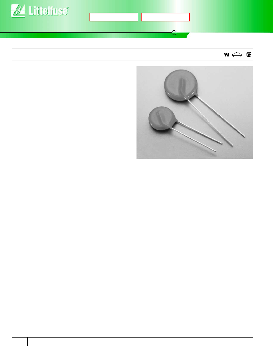
Line Voltage Operation, Radial Lead
The LA Series of transient voltage surge suppressors are radial-lead
varistors (MOVs) that are designed to be operated continuously across
AC power lines. These UL recognized varistors require very little
mounting space, and are offered in various standard lead form options.
The LA Series varistors are available in four model sizes: 7mm, 10mm,
14mm and 20mm; and have a VM(AC)RMS voltage range from 130V
to 1000V, and an energy absorption capability up to 360J. Some LA
series model numbers are available with clamping voltage selections,
designated by a model number suffix of either A or B. The "A" selection is
the standard model; the "B" selection provides a lower clamping voltage.
See LA Series Device Ratings and Specifications table for part number
and brand information.
Features
∑ Energy Absorption Capability (WTM) . . .. . . . . . . . . . . . . . . . . Up to 360J
∑ Wide Operating Voltage Range
VM(AC)RMS . . . . . . . . . . . . . . . . . . . . . . . . . . . . . . . . . . . . . 130V to 1000V
∑ No Derating Up to 85
o
C Ambient
∑ Available in Tape and Reel or Bulk Pack
AGENCY APPROVALS:
Recognized under the components program of
Underwriters Laboratories. Certified by CSA, VDE and CECC.
AGENCY FILE NUMBERS:
UL E75961, E56529, E135010; CSA
LR91788; VDE 116895E; CECC 42201-006.
ALSO SEE LITTELFUSE ULTRAMOV
TM
AND C-III VARISTOR SERIES
Æ
Æ
V
D
E
Next
Previous
2
V
ARIST
OR
PR
ODUCTS
LA Varistor Series
Varistor Products
Line Voltage Operation, Radial Lead
51
w w w . l i t t e l f u s e . c o m
Absolute Maximum Ratings
For ratings of individual members of a series, see Device Ratings and Specifications chart
Continuous:
Steady State Applied Voltage:
AC Voltage Range (VM(AC)RMS) . . . . . . . . . . . . . . . . . . . . . . . . . . . . . . . . . . . . . . . . . . . . . . . . . . . . . . . . . . . . . . . . . 130 to 1000
V
DC Voltage Range (VM(DC)) . . . . . . . . . . . . . . . . . . . . . . . . . . . . . . . . . . . . . . . . . . . . . . . . . . . . . . . . . . . . . . . . . . . . 175 to 1200
V
Transients:
Peak Pulse Current (ITM)
For 8/20µs Current Wave (See Figure 2) . . . . . . . . . . . . . . . . . . . . . . . . . . . . . . . . . . . . . . . . . . . . . . . . . . . . . . . . . . . 1200 to 6500
A
Single Pulse Energy Range
For 10/1000µs Current Wave (WTM ) . . . . . . . . . . . . . . . . . . . . . . . . . . . . . . . . . . . . . . . . . . . . . . . . . . . . . . . . . . . . . . . 11 to 360
J
Operating Ambient Temperature Range (TA) . . . . . . . . . . . . . . . . . . . . . . . . . . . . . . . . . . . . . . . . . . . . . . . . . . . . . . . . . . . . -55 to 85
0
C
Storage Temperature Range (TSTG) . . . . . . . . . . . . . . . . . . . . . . . . . . . . . . . . . . . . . . . . . . . . . . . . . . . . . . . . . . . . . . . . . -55 to 125
0
C
Temperature Coefficient (
V) of Clamping Voltage (VC) at Specified Test Current . . . . . . . . . . . . . . . . . . . . . . . . . . . . . . . . . <0.01
%/
0
C
Hi-Pot Encapsulation (Isolation Voltage Capability) . . . . . . . . . . . . . . . . . . . . . . . . . . . . . . . . . . . . . . . . . . . . . . . . . . . . . . . . . 2500
V
(Dielectric must withstand indicated DC voltage for one minute per MIL-STD 202, Method 301)
Insulation Resistance . . . . . . . . . . . . . . . . . . . . . . . . . . . . . . . . . . . . . . . . . . . . . . . . . . . . . . . . . . . . . . . . . . . . . . . . . . . . . . . 1000
M
CAUTION: Stresses above those listed in "Absolute Maximum Ratings" may cause permanent damage to the device. This is a stress only rating and operation of the device at these
or any other conditions above those indicated in the operational sections of this specification is not implied.
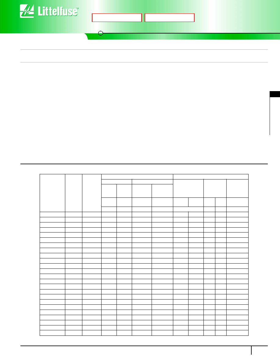
Device Ratings and Specifications
PART
NUMBER
MODEL
SIZE
DISC
DIA.
(mm)
DEVICE
MODEL
NUMBER
BRAND-
ING
MAXIMUM RATING (85
o
C)
SPECIFICATIONS (25
o
C)
CONTINUOUS
TRANSIENT
VARISTOR VOLT-
AGE AT 1mA DC
TEST CURRENT
MAXIMUM
CLAMPING
VOLTAGE
8 x 20
µs
TYPICAL
CAPACI-
TANCE
f = 1MHz
V
RMS
V
DC
ENERGY
10 x 1000
µs
PEAK
CURRENT
8 x 20
µs
V
M(AC)
V
M(DC)
W
TM
I
TM
V
NOM
MIN
V
NOM
MAX
V
C
I
PK
C
(V)
(V)
(J)
(A)
(V)
(V)
(A)
(pF)
V130LA1
7
1301
130
175
11
1200
184
255
390
10
180
V130LA2
7
1302
130
175
11
1200
184
228
340
10
180
V130LA5
10
1305
130
175
20
2500
184
228
340
25
450
V130LA10A
14
130L10
130
175
38
4500
184
228
340
50
1000
V130LA20A
20
130L20
130
175
70
6500
184
228
340
100
1900
V130LA20B
20
130L20B
130
175
70
6500
184
220
325
100
1900
V140LA2
7
1402
140
180
12
1200
198
242
360
10
160
V140LA5
10
1405
140
180
22
2500
198
242
360
25
400
V140LA10A
14
140L10
140
180
42
4500
198
242
360
50
900
V140LA20A
20
140L20
140
180
75
6500
198
242
340
100
1750
V150LA1
7
1501
150
200
13
1200
212
284
430
10
150
V150LA2
7
1502
150
200
13
1200
212
268
395
10
150
V150LA5
10
1505
150
200
25
2500
212
268
395
25
360
V150LA10A
14
150L10
150
200
45
4500
212
268
395
50
800
V150LA20A
20
150L20
150
200
80
6500
212
268
395
100
1600
V150LA20B
20
150L20B
150
200
80
6500
212
243
360
100
1600
V175LA2
7
1752
175
225
15
1200
247
303
455
10
130
V175LA5
10
1755
175
225
30
2500
247
303
455
25
350
V175LA10A
14
175L10
175
225
55
4500
247
303
455
50
700
V175LA20A
20
175L20
175
225
90
6500
247
303
455
100
1400
V230LA4
7
2304
230
300
20
1200
324
396
595
10
100
V230LA10
10
230L
230
300
35
2500
324
396
595
25
250
V230LA20A
14
230L20
230
300
70
4500
324
396
595
50
550
V230LA40A
20
230L40
230
300
122
6500
324
396
595
100
1100
LA SERIES UNITS
Next
Previous
Line Voltage Operation, Radial Lead
LA Varistor Series
Varistor Products
52
w w w . l i t t e l f u s e . c o m
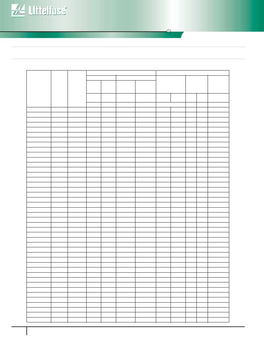
Device Ratings and Specifications
(Continued)
V250LA2
7
2502
250
330
21
1200
354
473
730
10
90
V250LA4
7
2504
250
330
21
1200
354
429
650
10
90
V250LA10
10
250L
250
330
40
2500
354
429
650
25
220
V250LA20A
14
250L20
250
330
72
4500
354
429
650
50
500
V250LA40A
20
250L40
250
330
130
6500
354
429
650
100
1000
V250LA40B
20
250L40B
250
330
130
6500
354
413
620
100
1000
V275LA2
7
2752
275
369
23
1200
389
515
775
10
80
V275LA4
7
2754
275
369
23
1200
389
473
710
10
80
V275LA10
10
275L
275
369
45
2500
389
473
710
25
200
V275LA20A
14
275L20
275
369
75
4500
389
473
710
50
450
V275LA40A
20
275L40
275
369
140
6500
389
473
710
100
900
V275LA40B
20
275L40B
275
369
140
6500
389
453
680
100
900
V300LA2
7
3002
300
405
25
1200
420
565
870
10
70
V300LA4
7
3004
300
405
25
1200
420
517
775
10
70
V300LA10
10
300L
300
405
46
2500
420
517
775
25
180
V300LA20A
14
300L20
300
405
77
4500
420
517
775
50
400
V300LA40A
20
300L40
300
405
165
6500
420
517
775
100
800
V320LA7
7
3207
320
420
25
1200
462
565
850
10
65
V320LA10
10
320L
320
420
48
2500
462
565
850
25
170
V320LA20A
14
320L20
320
420
80
4500
462
565
850
50
380
V320LA40B
20
320L40
320
420
150
6500
462
540
810
100
750
V385LA7
7
3857
385
505
27
1200
558
682
1025
10
60
V385LA10
10
385L
385
505
51
2500
558
682
1025
25
160
V385LA20A
14
385L20
385
505
85
4500
558
682
1025
50
360
V385LA40B
20
385L40
385
505
160
6500
558
682
1025
100
700
V420LA7
7
4207
420
560
30
1200
610
748
1120
10
55
V420LA10
10
420L
420
560
55
2500
610
748
1120
25
140
V420LA20A
14
420L20
420
560
90
4500
610
748
1120
50
300
V420LA40B
20
420L40
420
560
160
6500
610
720
1060
100
600
V460LA7
7
4607
460
615
37
1200
702
858
1130
10
55
V480LA7
7
4807
480
640
35
1200
670
825
1240
10
50
V480LA10
10
480L
480
640
60
2500
670
825
1240
25
120
V480LA40A
14
480L40
480
640
105
4500
670
825
1240
50
270
V480LA80B
20
480L80
480
640
180
6500
670
790
1160
100
550
V510LA10
10
510L
510
675
63
2500
735
910
1350
25
100
V510LA40A
14
510L40
510
675
110
4500
735
910
1350
50
250
V510LA80B
20
510L80
510
675
190
6500
735
860
1280
100
500
V575LA10
10
575L
575
730
65
2500
805
1000
1500
25
90
V575LA40A
14
575L40
575
730
120
4500
805
1000
1500
50
220
V575LA80B
20
575L80
575
730
220
6500
805
960
1410
100
450
V625LA10
10
625L
625
825
67
2500
900
1100
1650
25
80
V625LA40A
14
625L40
625
825
125
4500
900
1100
1650
50
210
V625LA80B
20
625L80
625
825
230
6500
900
1100
1650
100
425
PART
NUMBER
MODEL
SIZE
DISC
DIA.
(mm)
DEVICE
MODEL
NUMBER
BRAND-
ING
MAXIMUM RATING (85
o
C)
SPECIFICATIONS (25
o
C)
CONTINUOUS
TRANSIENT
VARISTOR VOLT-
AGE AT 1mA DC
TEST CURRENT
MAXIMUM
CLAMPING
VOLTAGE
8 x 20
µ
s
TYPICAL
CAPACI-
TANCE
f = 1MHz
V
RMS
V
DC
ENERGY
10 x 1000
µ
s
PEAK
CURRENT
8 x 20
µ
s
V
M(AC)
V
M(DC)
W
TM
I
TM
V
NOM
MIN
V
NOM
MAX
V
C
I
PK
C
(V)
(V)
(J)
(A)
(V)
(V)
(A)
(pF)
2
V
ARIST
OR
PR
ODUCTS
LA Varistor Series
Varistor Products
Line Voltage Operation, Radial Lead
53
w w w . l i t t e l f u s e . c o m
Device Ratings and Specifications
(Continued)
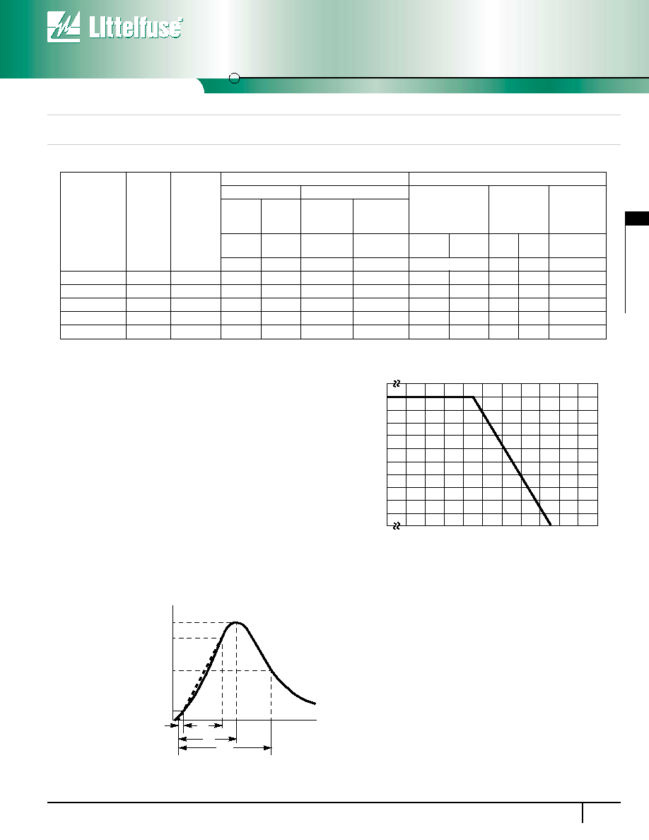
Power Dissipation Ratings
Should transients occur in rapid succession, the average power dissipation
is the energy (watt-seconds) per pulse times the number of pulses per
second. The power so developed must be within the specifications shown
on the Device Ratings and Specifications table for the specific device.The
operating values of a MOV need to be derated at high temperatures as
shown in Figure 1. Because varistors only dissipate a relatively small
amount of average power they are not suitable for repetitive applications
that involve substantial amounts of average power dissipation.
V660LA10
10
660L
660
850
70
2500
940
1250
1650
25
70
V660LA50A
14
660L50
660
850
140
4500
940
1250
1650
50
200
V660LA100B
20
660L100
660
850
250
6500
940
1250
1650
100
400
V1000LA80A
14
1000L80
1000
1200
220
4500
1425
1800
2700
50
130
V1000LA160B
20
1000L160
1000
1200
360
6500
1425
1600
2420
100
250
NOTE: Average power dissipation of transients not to exceed 0.25W, 0.4W, 0.6W or 1W for model sizes 7mm, 10mm, 14mm and 20mm, respectively.
PART
NUMBER
MODEL
SIZE
DISC
DIA.
(mm)
DEVICE
MODEL
NUMBER
BRAND-
ING
MAXIMUM RATING (85
o
C)
SPECIFICATIONS (25
o
C)
CONTINUOUS
TRANSIENT
VARISTOR VOLT-
AGE AT 1mA DC
TEST CURRENT
MAXIMUM
CLAMPING
VOLTAGE
8 x 20
µ
s
TYPICAL
CAPACI-
TANCE
f = 1MHz
V
RMS
V
DC
ENERGY
10 x 1000
µ
s
PEAK
CURRENT
8 x 20
µ
s
V
M(AC)
V
M(DC)
W
TM
I
TM
V
NOM
MIN
V
NOM
MAX
V
C
I
PK
C
(V)
(V)
(J)
(A)
(V)
(V)
(A)
(pF)
100
90
80
70
60
50
40
30
20
10
0
-55
50
60
70
80
90
100
110
120
130
140 150
AMBIENT TEMPERATURE (
o
C)
PERCENT OF RA
TED
V
ALUE
FIGURE 1. CURRENT, ENERGY AND POWER DERATING
CURVE
FIGURE 2. PEAK PULSE CURRENT TEST WAVEFORM
100
90
50
10
O
1
T
T
1
T
2
TIME
PERCENT OF PEAK V
ALUE
O
1
= Virtual Origin of Wave
T = Time From 10% to 90% of Peak
T
1
= Virtual Front time = 1.25 ∑ t
T
2
= Virtual Time to Half Value (Impulse Duration)
Example: For an 8/20
µ
s Current Waveform:
8
µ
s = T
1
= Virtual Front Time
20
µ
s = T
2
= Virtual Time to Half Value
Line Voltage Operation, Radial Lead
LA Varistor Series
Varistor Products
54
w w w . l i t t e l f u s e . c o m
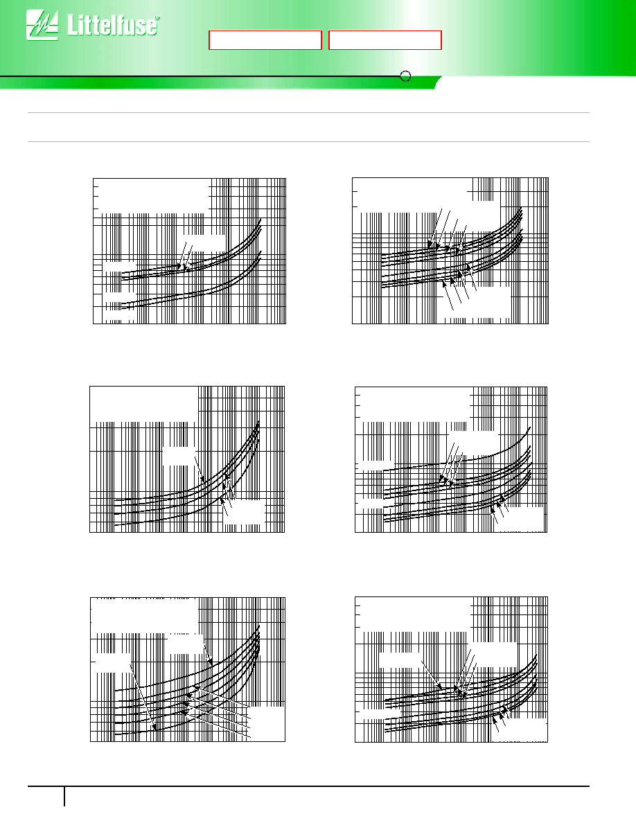
Transient V-I Characteristics Curves
FIGURE 3. CLAMPING VOLTAGE FOR V130LA1 - V300LA2
FIGURE 4. CLAMPING VOLTAGE FOR V130LA2 - V300LA4
FIGURE 5. CLAMPING VOLTAGE FOR V320LA7 - V480LA7
FIGURE 6. CLAMPING VOLTAGE FOR V130LA5 - V420LA10
FIGURE 7. CLAMPING VOLTAGE FOR V300LA10 - V660LA10
FIGURE 8. CLAMPING VOLTAGE FOR V130LA10A - V320LA20A
200
6,000
5,000
4,000
3,000
1,000
900
800
700
600
500
400
300
10
-3
10
-2
10
-1
10
0
10
1
10
2
10
4
MAXIMUM PEAK
V
O
L
TS (V)
PEAK AMPERES (A)
2,000
10
3
V150LA1
V130LA1
V300LA2
V275LA2
V250LA2
MAXIMUM CLAMPING VOLTAGE
MODEL SIZE 7mm
130 TO 300V
M(AC)
RATING
T
A
= -55
o
C TO 85
o
C
10
-3
10
-2
10
-1
10
0
10
1
10
2
10
4
MAXIMUM PEAK
V
O
L
TS (V)
PEAK AMPERES (A)
10
3
4,000
3,000
2,000
1,000
900
800
700
600
500
400
300
200
100
MAXIMUM CLAMPING VOLTAGE
MODEL SIZE 7mm
130 TO 300V
M(AC)
RATING
T
A
= -55
o
C TO 85
o
C
V300LA4
V275LA4
V250LA4
V230LA4
V130LA2
V140LA2
V150LA2
V175LA2
MAXIMUM CLAMPING VOLTAGE
MODEL SIZE 7mm
T
A
= -55
o
C TO 85
o
C
320 TO 480V
M(AC)
RATING
V420LA7
V385LA7
V320LA7
V460LA7
V480LA7
10
-3
10
-2
10
-1
10
0
10
1
10
2
10
4
10
3
5,000
3,000
2,000
1,000
500
PEAK AMPERES (A)
MAXIMUM PEAK
V
O
L
TS (V)
200
6,000
5,000
4,000
3,000
1,000
900
800
700
600
500
400
300
10
-3
10
-2
10
-1
10
0
10
1
10
2
10
4
MAXIMUM PEAK
V
O
L
TS (V)
PEAK AMPERES (A)
2,000
10
3
V275LA10
V250LA10
MAXIMUM CLAMPING VOLTAGE
MODEL SIZE 10mm
130 TO 420V
M(AC)
RATING
T
A
= -55
o
C TO 85
o
C
V230LA10
V420LA10
V175LA5
V130LA5
V140LA5
V150LA5
10
-3
10
-2
10
-1
10
0
10
1
10
2
10
4
10
3
5,000
3,000
2,000
1,000
500
V575LA10
V510LA10
V480LA10
V385LA10
V300LA10
V320LA10
PEAK AMPERES (A)
V625LA10
V660LA10
MAXIMUM CLAMPING VOLTAGE
MODEL SIZE 10mm
T
A
= -55
o
C TO 85
o
C
300 TO 660V
M(AC)
RATING
MAXIMUM PEAK
V
O
L
TS (V)
200
6,000
5,000
4,000
3,000
1,000
900
800
700
600
500
400
300
10
-3
10
-2
10
-1
10
0
10
1
10
2
10
4
MAXIMUM PEAK
V
O
L
TS (V)
PEAK AMPERES (A)
2,000
10
3
V275LA20A
V250LA20A
MAXIMUM CLAMPING VOLTAGE
MODEL SIZE 14mm
130 TO 320V
M(AC)
RATING
T
A
= -55
o
C TO 85
o
C
V230LA20A
V175LA10A
V130LA10A
V140LA10A
V150LA10A
V320LA20A
V300LA20A
Next
Previous