DEVICES INCORPORATED
Special Arithmetic Functions
08/16/2000≠LDS.33-O
1
LSH33
32-bit Barrel Shifter with Registers
u
u
u
u
u 32-bit Input, 32-bit Output Multi-
plexed to 16 Lines
u
u
u
u
u Full 0-31 Position Barrel Shift
Capability
u
u
u
u
u Integral Priority Encoder for 32-bit
Floating Point Normalization
u
u
u
u
u Sign-Magnitude or Two's Comple-
ment Mantissa Representation
u
u
u
u
u 32-bit Linear Shifts with Sign or
Zero Fill
u
u
u
u
u Independent Priority Encoder
Outputs for Block Floating Point
u
u
u
u
u
68-pin PLCC, J-Lead
FEATURES
DESCRIPTION
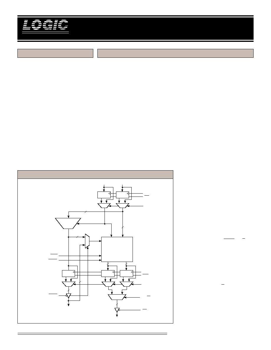
LSH33
32-bit Barrel Shifter with Registers
DEVICES INCORPORATED
LSH33 B
LOCK
D
IAGRAM
The LSH33 is a 32-bit high speed
shifter designed for use in floating
point normalization, word pack/
unpack, field extraction, and similar
applications. It has 32 data inputs,
and 16 output lines. Any shift con-
figuration of the 32 inputs, including
circular (barrel) shifting, left shifts
with zero fill, and right shifts with
sign extension are possible. In addi-
tion, a built-in priority encoder is
provided to aid floating point normal-
ization.
Input/Output registers provide
complete pipelined operation. Both
have independent bypass paths for
complete flexibility. When FTI = 1,
the input registers are bypassed.
Likewise, when FTO= 1, the output
registers are bypassed.
SHIFT ARRAY
The 32 inputs, which can be regis-
tered, to the LSH33 are applied to a
32-bit shift array. The 32 outputs,
which can also be registered, of this
array are then multiplexed down to
16 lines for presentation at the device
outputs. The array may be configured
such that any contiguous 16-bit field
(including wraparound of the 32
inputs) may be presented to the
output pins under control of the shift
code field (wrap mode). Alterna-
tively, the wrap feature may be
disabled, resulting in zero or sign bit
fill, as appropriate (fill mode). The
shift code control assignments and the
resulting input to output mapping for
the wrap mode are shown in Table 1.
Essentially the LSH33 is configured as
a left shift device. That is, a shift code
of 00000
2
results in no shift of the
input field. A code of 00001
2
provides
an effective left shift of 1 position, etc.
When viewed as a right shift, the shift
code corresponds to the two's comple-
ment of the shift distance, i.e., a shift
code of 11111
2
(≠1
10
) results in a right
shift of one position, etc.
When not in the wrap mode, the
LSH33 fills bit positions for which
there is no corresponding input bit.
The fill value and the positions filled
depend on the RIGHT/LEFT (R/L)
direction pin. This pin is a don't care
input when in wrap mode. For left
shifts in fill mode, lower bits are filled
with zero as shown in Table 2. For
right shifts, however, the SIGN input
is used as the fill value. Table 3
depicts the bits to be filled as a
function of shift code for the right shift
case. Note that the R/L input changes
only the fill convention, and does not
affect the definition of the shift code.
16
OE
MS/LS
32-bit
BARREL
SHIFT
ARRAY
16
2:1
32:5
PRIORITY
ENCODE
32
5
32
SIGN
NORM
RIGHT/LEFT
FILL/WRAP
5
G
G
2:1
G
G
2:1
2:1
2:1
2:1
ENO
CLK
ENI
CLK
FTO
FTI
G
2:1
5
I
31
-I
0
Y
15
-Y
0
SI/O
4
-SI/O
0
16

DEVICES INCORPORATED
Special Arithmetic Functions
08/16/2000≠LDS.33-O
5
LSH33
32-bit Barrel Shifter with Registers
1234567890123
1234567890123
1234567890123
1234567890123
1234567890123
1234567890123
1234567890123
1234567890123
1234567890123
1234567890123
1234567890123
1234567890123
1234567890123
1234567890123
1234567890123
1234567890123
1234567890123
1234567890123
1234567890123
1234567890123
1234567890123
1234567890123
1234567890123
1234567890123
1234567890123
1234567890123
1234567890123
1234567890123
1234567890123
1234567890123
1234567890123
1234567890123
1234567890123
1234567890123
1234567890123
1234567890123
1234567890123
1234567890123
1234567890123
1234567890123
1234567890123
1234567890123
1234567890123
1234567890123
1234567890123
1234567890123
1234567890123
1234567890123
1234567890123
1234567890123
1234567890123
1234567890123
1234567890123
1234567890123
1234567890123
1234567890123
1234567890123
1234567890123
123456789012345678901234567
123456789012345678901234567
123456789012345678901234567
123456789012345678901234567
123456789012345678901234567
123456789012345678901234567
123456789012345678901234567
123456789012345678901234567
123456789012345678901234567
123456789012345678901234567
123456789012345678901234567
123456789012345678901234567
123456789012345678901234567
123456789012345678901234567
123456789012345678901234567
123456789012345678901234567
123456789012345678901234567
123456789012345678901234567
123456789012345678901234567
123456789012345678901234567
123456789012345678901234567
123456789012345678901234567
123456789012345678901234567
123456789012345678901234567
123456789012345678901234567
123456789012345678901234567
123456789012345678901234567
123456789012345678901234567
123456789012345678901234567
123456789012345678901234567
123456789012345678901234567
123456789012345678901234567
123456789012345678901234567
123456789012345678901234567
123456789012345678901234567
123456789012345678901234567
123456789012345678901234567
123456789012345678901234567
123456789012345678901234567
123456789012345678901234567
123456789012345678901234567
123456789012345678901234567
123456789012345678901234567
123456789012345678901234567
123456789012345678901234567
123456789012345678901234567
123456789012345678901234567
123456789012345678901234567
123456789012345678901234567
123456789012345678901234567
123456789012345678901234567
123456789012345678901234567
123456789012345678901234567
123456789012345678901234567
123456789012345678901234567
123456789012345678901234567
123456789012345678901234567
123456789012345678901234567
123456789012345678901234567
123456789012345678901234567
123456789012345678901234567
123456789012345678901234567
123456789012345678901234567
123456789012345678901234567
123456789012345678901234567
123456789012345678901234567
123456789012345678901234567
123456789012345678901234567
123456789012345678901234567
123456789012345678901234567
123456789012345678901234567
123456789012345678901234567
123456789012345678901234567
123456789012345678901234567
123456789012345678901234567
123456789012345678901234567
123456789012345678901234567
123456789012345678901234567
123456789012345678901234567
123456789012345678901234567
123456789012345678901234567
123456789012345678901234567
123456789012345678901234567
123456789012345678901234567
123456789012345678901234567
123456789012345678901234567
123456789012345678901234567
123456789012345678901234567
123456789012345678901234567
123456789012345678901234567
123456789012345678901234567
123456789012345678901234567
123456789012345678901234567
123456789012345678901234567
123456789012345678901234567
123456789012345678901234567
123456789012345678901234567
123456789012345678901234567
123456789012345678901234567
123456789012345678901234567
123456789012345678901234567
123456789012345678901234567
123456789012345678901234567
123456789012345678901234567
123456789012345678901234567
123456789012345678901234567
123456789012345678901234567
123456789012345678901234567
123456789012345678901234567
123456789012345678901234567
123456789012345678901234567
123456789012345678901234567
123456789012345678901234567
123456789012345678901234567
123456789012345678901234567
123456789012345678901234567
123456789012345678901234567
123456789012345678901234567
123456789012345678901234567
123456789012345678901234567
123456789012345678901234567
123456789012345678901234567
123456789012345678901234567
123456789012345678901234567
123456789012345678901234567
123456789012345678901234567
123456789012345678901234567
123456789012345678901234567
123456789012345678901234567
123456789012345678901234567
123456789012345678901234567
123456789012345678901234567
123456789012345678901234567
123456789012345678901234567
123456789012345678901234567
123456789012345678901234567
123456789012345678901234567
123456789012345678901234567
123456789012345678901234567
123456789012345678901234567
123456789012345678901234567
123456789012345678901234567
123456789012345678901234567
123456789012345678901234567
123456789012345678901234567
123456789012345678901234567
123456789012345678901234567
123456789012345678901234567
123456789012345678901234567
123456789012345678901234567
123456789012345678901234567
123456789012345678901234567
123456789012345678901234567
123456789012345678901234567
123456789012345678901234567
123456789012345678901234567
123456789012345678901234567
123456789012345678901234567
123456789012345678901234567
123456789012345678901234567
123456789012345678901234567
123456789012345678901234567
123456789012345678901234567
123456789012345678901234567
123456789012345678901234567
123456789012345678901234567
123456789012345678901234567
123456789012345678901234567
123456789012345678901234567
123456789012345678901234567
123456789012345678901234567
123456789012345678901234567
123456789012345678901234567
123456789012345678901234567
123456789012345678901234567
123456789012345678901234567
123456789012345678901234567
123456789012345678901234567
LSH33-40*
Y
15
-Y
0
SO
4
-SO
0
28
28
28
--
73
/
40
55
/
--
52
--
52
--
28
--
28
28
28
--
73
/
40
55
/
--
52
--
52
--
28
--
SWITCHING CHARACTERISTICS -- C
OMMERCIAL
O
PERATING
R
ANGE
(0∞C to +70∞C)
G
UARANTEED
M
AXIMUM
C
OMBINATIONAL
D
ELAYS
Notes 9, 10 (ns)
To Output
From Input
FTI = 0, FTO = 0
CLK
MS/LS
FTI = 0, FTO= 1
CLK (NORM = 0/1)
SI
4
-SI
0
R/L, F/W
MS/LS
FTI = 1, FTO = 0
CLK
MS/LS
FTI = 1, FTO = 1
I
31
-I
0
, SIGN
(NORM = 0/1)
SI
4
-SI
0
R/L, F/W
MS/LS
LSH33-30
Y
15
-Y
0
SO
4
-SO
0
24
24
24
--
58
/
30
42
/
--
40
--
40
--
24
--
24
24
24
--
58
/
30
42
/
--
40
--
40
--
24
--
LSH33-20*
Y
15
-Y
0
SO
4
-SO
0
15
15
15
--
20
/
20
20
/
--
20
--
20
--
15
--
15
15
15
--
20
/
20
20
/
--
20
--
20
--
15
--
Input
I
31
-I
0
, SIGN
SI
4
-SI
0
R/L, F/W
ENI, ENO
G
UARANTEED
M
INIMUM
S
ETUP
AND
H
OLD
T
IMES
W
ITH
R
ESPECT
TO
C
LOCK
R
ISING
E
DGE
Notes 9, 10 (ns)
LSH33-30
FTI = 0
FTI = 1
Setup Hold
Setup Hold
10
3
15
2
15
0
15
0
10
0
10
0
10
0
10
0
LSH33-20*
FTI = 0
FTI = 1
Setup Hold
Setup Hold
8
0
8
2
8
0
8
0
8
0
8
0
8
0
8
0
LSH33-40*
FTI = 0
FTI = 1
Setup Hold
Setup Hold
12
3
20
2
17
0
17
0
12
0
12
0
12
0
12
0
T
RI
-S
TATE
E
NABLE
/D
ISABLE
T
IMES
Notes 9, 10, 11 (ns)
LSH33-40*
LSH33-30
LSH33-20*
20
17
15
20
17
15
t
ENA
t
DIS
C
LOCK
C
YCLE
T
IME
AND
P
ULSE
W
IDTH
Notes 9, 10 (ns)
Minimum Cycle Time
Highgoing Pulse
Lowgoing Pulse
LSH33-40*
LSH33-30
LSH33-20*
30
20
15
12
9
7
12
9
7
123456789012345678901234
123456789012345678901234
123456789012345678901234
123456789012345678901234
*D
ISCONTINUED
S
PEED
G
RADE


