 | –≠–ª–µ–∫—Ç—Ä–æ–Ω–Ω—ã–π –∫–æ–º–ø–æ–Ω–µ–Ω—Ç: EM2H | –°–∫–∞—á–∞—Ç—å:  PDF PDF  ZIP ZIP |

Ether Module - EM2H
10Base-2
1
MD400153/B
Introduction
The Thin Net (Cheapernet) module provides a complete
Local Area Network interface for a station, without a
transceiver cable. The EM2H is an encased module
containing all circuit components for a complete Thin Net
COAX interface and includes an on-board SEEQ CMOS
83C92C transceiver DC/DC converter and isolation trans-
former.
The module is compatible with ANSI/IEEE 802.3 and ISO
8802-3.
The module is part of a chipset manufactured by SEEQ
Technology to provide the basic components for a LAN
interface board. The other components include the
80C03, 8005/80C04A Advanced Ethernet Data Link Con-
trollers (AEDLC
TM
), the 8020 or 8023A Manchester Code
Converter (MCC
TM
), and the 80C24 Media Interface
adapter (MIA).
Features
s
The module is compatible with ANSI/IEEE 802.3
and ISO 8802-3 Standards for Thin Net (10BASE2).
s
Contains all Thin Net COAX transceiver functions
within a single encased unit.
s
Squelch circuits on all signal inputs to eliminate
noise.
Ether Module
TM
-EM2H
10Base-2
Ethernet Transceiver Module with on Board
Isolation Transformer & DC/DC Converter
97176
s
Collision Test Generator, externally deselectable to
work with any ANSI/IEEE 802.3 and ISO 8802-3
repeater.
s
Detects and reports network collisions in both
transmit and receive modes.
s
Implemented with SEEQ proprietary high voltage
(20V) and high performance CMOS process.
s
Loopback test detects network cable opens or
shorts.
s
Power On Reset prevents transmission during
power up.
s
Regulated DC to DC Converter on board.
s
Disable pin to power-down module.
s
Isolation Transformer on board.
s
Optimized for Hub and Repeater Applications.
s
EM2H is Available for Adapter Card Applications
AEDLC, MCC and Ether Module are trademarks of SEEQ Technology, Inc.
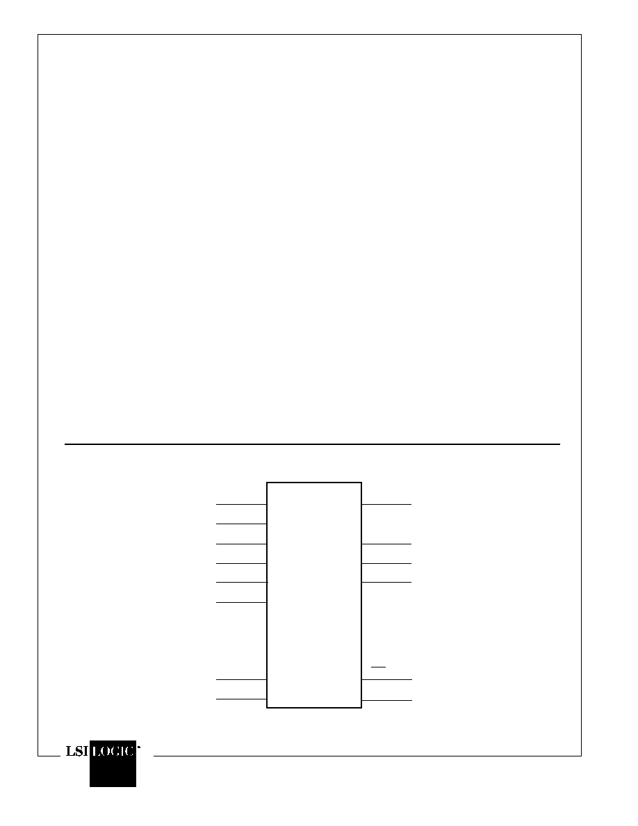
Figure 1. Ethernet Transceiver Module Block Diagram
COAX
CABLE
10 MHz
OSILLATOR
RX
SQUELCH
COLLISION
TEST
GENERATOR
JABBER
TIMER
TX
SQUELCH
TRANSMITTER
LOW PASS
FILTER
COLLISION
COMPARATOR
_
+
LINE
DRIVER
CD +
TX +
TX ≠
COLLISION
SIGNAL TO
STATION
TRANSMIT
FROM
STATION
CD ≠
+
≠
REGULATED
DC/DC
CONV
VCC
VEE
SYS GND
LINE DRIVER
RX +
RX ≠
RECEIVE
TO STATION
1:1
1:1
1:1
DM
18
6
5
12
9
10
11
2
1
4
3
V
EE
1.0 K
1.0
K
V
EE
GND
1.0
K
V
EE
1.0
K
V
EE
9
10
Note: Check for latest Data Sheet revision
before starting any designs.
SEEQ Data Sheets are now on the Web, at
www.lsilogic.com.
This document is an LSI Logic document. Any
reference to SEEQ Technology should be
considered LSI Logic.
Ether Module - EM2H
10Base-2
MD400153/B
2
CD +
CD ≠
RX +
RX ≠
TX +
TX ≠
1
2
3
4
5
6
9
10
CDS
20
HBE
16
12
11
SYS GND
CC
V
VEE
DM
RXI
18
17
TXO
[1]
Description
The Thin Net module connects the station equipment to a
Thin Net (Cheapernet) COAX cable. The on-board
83C92C CMOS COAX transceiver provides the drive
current and wave shaping for the transmit signals. It
supplies receive signal equalization, collision detection
and squelch.
Description of the Pin Functions
PIN #
FUNCTION
1 - 2
CD
±
Collision Output. A balanced 10 MHz
differential output to the station equipment when
a collision is detected, when excessive data
transmission occurs (jabber), or during the
Collision Test (Heartbeat Test).
3, 4
RX
±
Receive Data Output. Line Driver output to
the MCC Receive inputs.
11
V
EE
Negative Supply. Nominally ≠9 volts refer-
enced to COAX shield ground.
An on-board DC-DC power converter provides
≠9 volt power for the on-board module , and DC
isolation from the station equipment to prevent
ground loop current.
5 - 6
TX
±
Transmit Data Input. A balanced line re-
ceiver input to the module from the MCC for
transmit packets.
16
HBE Heartbeat Enable. This input enables
the Collision (also called Heartbeat) Test when
connected to ground, and disables the test when
connected to V
EE
.
10
SYS GND Ground. System Ground is
referenced to V
CC
.
18
RXI Network Signal Receiver. Connects to the
network COAX center conductor, and receives
packet data and detects the collision voltage
level.
17
TXO Network Signal Transmitter. Connects to
the network COAX center conductor through an
internal 1N916 diode, and transmits all signals
from the MCC to the network.
20
CDS Collision Detect Sense. Connects di-
rectly to the network shield, and references the
collision detection voltage level.
Figure 2. Ethernet Transceiver Module Pin Configuration
TOP VIEW
SYS GND
V CC

Ether Module - EM2H
10Base-2
3
MD400153/B
12
DM Disable module is an active low signal (inter-
nal 10K
pullup) that may be utilized to turn off
the Ether module in the event an alternative
transceiver is used, or for power conservation
purposes.
Description of the Module Functions
The module has five main functions, as shown in the block
diagram. These are the Transmitter; the Collision Detec-
tor; the Jabber Timer; the Receiver; and the DC/DC
Converter. The on-board SEEQ 83C92C provides all
functions except DC/DC conversion and AUI signal isola-
tion.
The Transmitter
The Transmitter takes differential output signals from the
MCC, and outputs these signals at the correct levels to the
network.
The transmit signal is sent to the module via a balanced
differential pair (TX
±
). A squelch circuit prevents the
Transmitter Output from responding to noise on the TX
±
pair. The Transmitter has an open-collector current driver
output using the V
EE
supply. Rise and fall times are
controlled and set at 25 ns/V to lessen the higher harmon-
ics. Drive current levels are set by a bandgap voltage
reference and a internal 1K resistor. An internal diode is
also added to reduce COAX loading and capacitance to
comply with the ISO and ANSI/IEEE specifications.
The transmit squelch circuit blocks signals with pulse
widths less than 15 nanoseconds, (negative-going), or
with levels of less than ≠175 millivolts. The squelch circuits
turn the Transmitter off at the end of a packet if the signal
stays higher than ≠175 millivolts for more than 190 nanos-
econds. See Figure 3, the Transmitter Timing Diagram.
The TXO signal is disabled when not transmitting to
prevent noise on the network. If the COAX cable is shorted
or open, no transmitted data appears on the Receiver
input. This condition can be detected by the station
equipment by running a loopback test.
Collision Detection
The Collision detector monitors the COAX Center Con-
ductor and senses the voltage conditions created by a
collision, where the COAX shield is used as a reference. A
collision condition can be detected when two or more
stations are transmitting, whether or not the local Trans-
mitter is activated. This is called Receive Mode Collision
Detection.
The detector signals a collision by sending the 10 MHz
oscillator signal through the Collision Pair (CD
±
) to the
MCC. The HeartbeatTest is performed at the end of each
transmitted data packet to verify the operation of the
detector.
A collision causes a ≠2.0 volt average DC level on the
center conductor of the network cable. This level passes
through a 4-pole Bessel low-pass filter for averaging. The
resulting signal is measured by a voltage comparator
against the threshold voltage V
CD
of about -1.5 volts. A
collision is indicated when the center conductor average
level is more negative than the CDS level by the threshold
V
CD
. The line driver is enabled within 900 ns of the onset
of the collision, and the 10 MHz signal is sent to the station
equipment.
The Heartbeat Test is a short burst of the collision signal
generated immediately after the transmission of a packet.
This test enables the 10 MHz collision signal for about 1
Figure 3. Transmitter Timing
TX±
TX0
t Td
50%
VTSQ
t Tf
t TON
t TST
VTSQ
t TOFF
50%
90%
10%
t Tr
TRANSMIT
ENABLE
tTID

Ether Module - EM2H
10Base-2
MD400153/B
4
A 4-pole Bessel low-pass filter provides the average DC
level from the received signal. It sends this level to the
Collision Comparator and RX Squelch circuits. The
squelch circuit activates the Receive Line Driver only when
it detects a true signal. This prevents noise triggering the
receiver.
When a packet is detected, the DC level from the Low-pass
Filter becomes more negative than the DC squelch thresh-
old, and the Receiver turns on. The squelch circuit AC
timing detects high level signals of more than 225 nanos-
econds, and turns the Receiver off. If within 1 microsecond
(typical) the low_pass filter level becomes more positive
than the DC squelch threshold, then the receiver stays off.
See the Receiver Timing Diagram, Figure 4.
The System Connections diagram shows the transceiver
connections in a station environment. RX
±
and CD
±
differential signals to the MCC are biased by 1.0 K ohm
pull-down resistors and are isolated from the MCC. The
DC supply is converted to ≠9V by a DC to DC converter.
This converter also provides DC isolation between the +5
volt and ≠9 volt sides.
The COAX center conductor connects to the Receive and
Transmit pins of the transceiver. An internal diode
minimizes network loading when power is on or off. COAX
tap capacitance contributed by the Thin Net module is less
microsecond starting about 1.1 microseconds after the
end of transmission. This test can be disabled for opera-
tion with repeaters by connecting the HBE pin to V
EE
.
The Jabber Timer
The Jabber Timer monitors the operation of the Transmit-
ter, using the 10 MHz Oscillator as a time base. If the
Transmitter operates continuously for more than typically
40 Milliseconds, the Jabber Timer disables the Transmit-
ter and enables the Collision Detector outputs. The
Transmitter is automatically re-enabled after the station
has been silent for 500 milliseconds.
The Receiver
The Receiver detects any signal on the COAX center
conductor that triggers its squelch circuits, and sends the
signal through a differential line driver to the MCC. The
Receiver provides amplification and equalization; a
squelch circuit prevents noise from activating the Receiver
circuits. See Figure 4.
The receive signal goes through a buffer with a high input
impedance and low capacitance to reduce loading and
reflections on the network COAX. An equalizer passes
high frequencies and attenuates low frequency signals
from the network, flattening the network pass band. The
signal is output through a differential line driver presenting
a balanced signal to the station. The line driver has 4
nanosecond rise and fall times.
Figure 4. Receiver Timing
RX±
RXI
tRON
50%
t Rd
90%
50%
tRf
RECEIVER
SQUELCH
LOW-PASS
FILTER
RECEIVE
ENABLE
DC
THRESHOLD
DC
THRESHOLD
1 µs
t

Ether Module - EM2H
10Base-2
5
MD400153/B
CD+
CD≠
8020
8023A
MANCHESTER
CODE
CONVERTER
RX+
RX≠
TX+
TX≠
OSC
CSN
COLL
RxC
TxEN
TxC
TxD
RxD
LPBK
CLK
DATA LINK
CONTROLLER
NCORE
80C04A
80C03
D0-D7
D8-D15
A0-A3
CONTROL
CPU
*
*
0.01
µF
39
1%
0.01
µF
39
1%
243
1% 1W
39
1%
39
1%
243
1% 1W
RX+
TX+
RX≠
TX≠
CD+
CD≠
CDS
EM2C
than 4 pF at 10 MHz, powered and unpowered, not
transmitting. CDS, Collision Detection Sense detects the
Collision reference level. This is a ground-referenced
sense pin. It should be connected directly to the COAX
shield to prevent ground-loop interference.
The Transceiver assembly includes the DC - DC Con-
verter and a pulse transformer for RX
±
, TX
±
and CD
±
signal isolation.
Figure 5a. Coax Ethernet Transceiver System Connections
10
9
EM2H