DB11-000045-01
May 2003
Copyright © 2003 by LSI Logic Corporation. All rights reserved.
Æ
Quick Hardware Setup Guide
LSI Logic LSI21320-R
Host Bus Adapter
Thank you for purchasing the LSI21320-R Host Bus Adapter (HBA).
Please take a few minutes to read this Quick Hardware Setup
Guide before you install the LSI21320-R. If you need more
information about any topic covered in this guide, please refer to
the other documents on the accompanying LSI Logic Host Bus
Adapter compact disk (CD).
Contents of the LSI Logic Host Bus Adapter CD
The LSI Logic Host Bus Adapter CD contains utility programs,
device drivers for various operating systems, and the following
documentation:
∑
LSI Logic Ultra320 SCSI to PCI-X Storage Adapter User's Guide
∑
LSI Logic Device Management User's Guide
∑
LSI Logic Host Bus Adapter technical product briefs
∑
Information on SCSI cables
Technical Support
For assistance installing, configuring, or running the LSI21320-R,
contact LSI Logic Technical Support:
Phone Support: 1-800-633-4545
Web Site: http://www.lsilogic.com
Storage Adapter Installation
Caution: Make a backup of your data before changing your system
configuration.
These steps install the LSI21320-R. The following text provides an
explanation of each step.
Step 1: Unpack Storage Adapter
Unpack the LSI21320-R in a static-free environment. Remove the
LSI21320-R from the antistatic bag and inspect it for damage. If it
appears to be damaged, or if the LSI Logic Host Bus Adapter CD
is missing, contact LSI Logic or your OEM support representative.
Step 2: Prepare Computer
Turn off the computer and remove the power cord from the back of
the power supply. Remove the cover from the chassis. Be certain
to disconnect the computer from the power and from any networks
before installing the controller card.
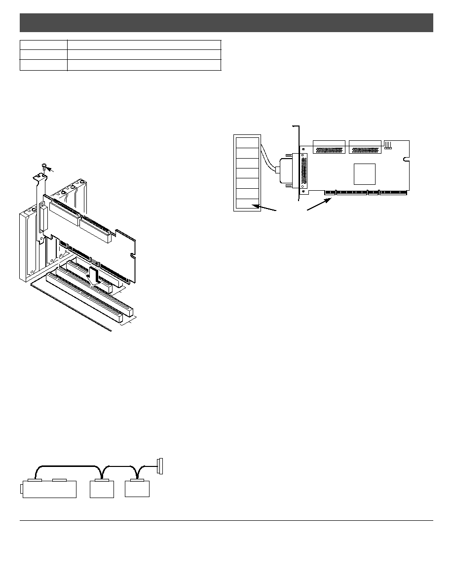
Step 3: Install LSI21320-R
Install the LSI21320-R in a 3.3 V or 5 V PCI slot, as shown in
Figure 2
. Press down gently, but firmly, to seat the card properly the
slot. The bottom edge of the controller card must be flush with the
slot. Then attach the LSI21320-R to the computer chassis with the
bracket screw. The LSI Logic Ultra320 SCSI to PCI-X Storage
Adapter User's Guide provides detailed instructions for installing
and configuring the LSI21320-R.
Step 4: Connect the SCSI Devices to the LSI21320-R
Connect SCSI devices to the internal high-density 68-pin SCSI
connectors and/or the external high-density 68-pin SCSI
connectors. To achieve maximum data throughput, use only
Ultra320 SCSI devices. The LSI21320-R supports up to 15 Ultra320
SCSI devices per channel and a maximum SCSI bus cable length
of 12 m.
Disable SCSI termination on all the devices that are not located at
the end of the SCSI bus. Use only high-quality ribbon SCSI cables
for internal devices and high-quality round SCSI cables for external
devices. If you are connecting both SCSI disk drives and other
kinds of SCSI devices, LSI Logic recommends that you connect the
disk drives on one SCSI channel and the other devices on the other
channel.
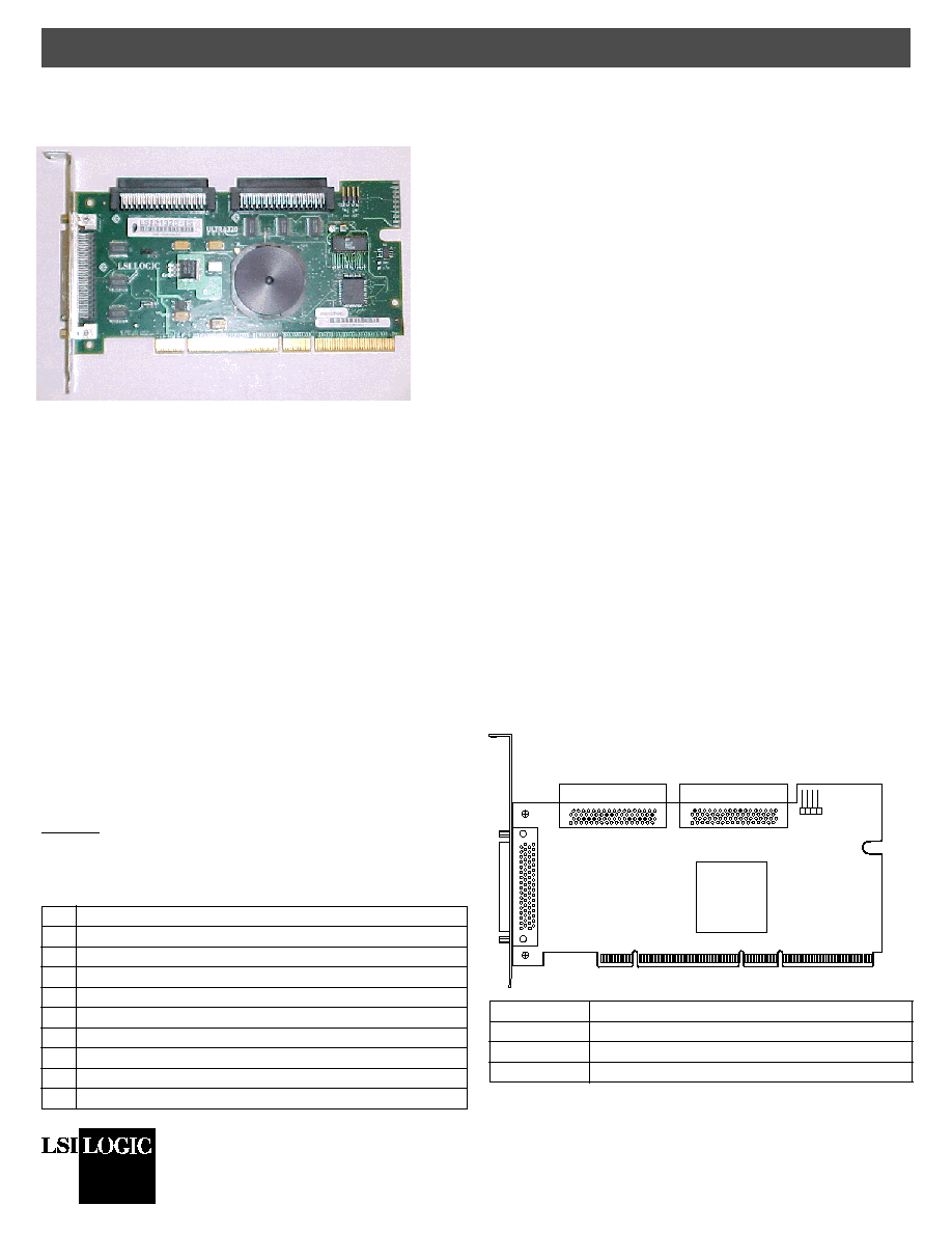
Figure 1
and the following table provide the location and
definition of the connectors on the LSI21320-R.
Figure 1 LSI21320-R Host Bus Adapter Board Drawing
Step Action
1
Unpack the LSI21320-R.
2
Turn off the computer, remove the power cord, and remove the cover.
3
Install the LSI21320-R in a PCI or PCI-X slot.
4
Connect the SCSI devices to the LSI21320-R.
5
Set the target IDs for the SCSI devices.
6
Set the SCSI termination.
7
Replace the computer cover and turn the power on.
8
Run the LSI Logic BIOS Configuration Utility.
9
Install the operating system device driver.
Connector
Definition
J1
PCI/PCI-X Connector
J2
External SCSI Channel A Connector
J3
Internal SCSI Channel B Connector
J1 - PCI/PCI-X
LSI53C1030
J2
Channel A
Ultra320 SCSI LVD/SE
J3
Channel B
Ultra320 SCSI LVD/SE
J6 for
Channels
A and B
J4
Channel A
Ultra320 SCSI LVD/SE
Quick Hardware Setup Guide
DB11-000045-01, May 2003
LSI Logic, the LSI Logic logo design, Integrated Mirroring, and Integrated Striping are
trademarks or registered trademarks of LSI Logic Corporation. All other brand and prod-
uct names may be trademarks of their respective companies.
You can find a list of LSI Logic Corporation's U.S. distributors, international distributors,
sales offices, and design resource centers on the LSI Logic web site at:
http://www.lsilogic.com/contacts/index.html
Copyright © 2003 by LSI Logic Corporation. All rights reserved.
LSI Logic Corporation reserves the right to make changes to any products and services
herein at any time without notice. LSI Logic does not assume any responsibility or liabil-
ity arising out of the application or use of any product or service described herein,
except as expressly agreed to in writing by LSI Logic; nor does the purchase, lease, or
use of a product or service from LSI Logic convey a license under any patent rights,
copyrights, trademark rights, or any other of the intellectual property rights of LSI Logic
or of third parties.
Step 5: Set Target IDs for SCSI Devices
Each connected SCSI device must have a unique Target ID (TID),
ranging from 0 to 15 for 16-bit devices. The LSI21320-R uses
TID 7, which is the highest priority TID. Verify that no two SCSI
devices on the same channel use the same TID; change the TIDs
as needed. See the SCSI device documentation for instructions
concerning changing the SCSI device's TID.
Figure 2 Inserting the Host Bus Adapter Board
Step 6: Set SCSI Termination
The SCSI bus, which consists of the SCSI bus cables and SCSI
devices, is an electrical transmission line that must be terminated
properly to minimize signal reflections and prevent data loss.
Enable SCSI termination at each end of each SCSI bus (channel)
and only at the ends of the SCSI bus. In
Figure 3
, internal SCSI
devices connect to one channel. The LSI21320-R automatically
terminates its end of the SCSI bus if only internal devices or only
external devices connect to that channel. The LSI21320-R
automatically disables termination if both internal and external
devices connect to that channel, because the LSI21320-R is then
in the "middle" of the SCSI bus.
Figure 3 SCSI Termination for Internal SCSI Devices
For a disk array, set the SCSI bus termination so that removing or
adding a SCSI device does not disturb termination. To do this,
connect the LSI21320-R to one end of the SCSI cable and connect
a SCSI terminator module at the other end of the cable. Attach
SCSI devices to the connectors between the two ends and disable
termination on them.
Figure 4
shows an external drive enclosure
with seven SCSI drives. Termination is enabled at the end of the
cable nearest the "last" SCSI drive, which is assigned TID 6.
Figure 4 SCSI Termination in a SCSI Disk Array
Some disk enclosures handle termination for the SCSI devices
within the enclosure. Refer to the enclosure documentation for
more information.
Step 7: Power Up the Computer
Replace the computer cover and connect the power cords. Turn on
the power to all the devices. Be sure the SCSI devices power up
before or at the same time as the computer. Otherwise, the
computer might not recognize the SCSI devices.
Step 8: Run the BIOS Configuration Utility
During boot, the following message appears:
Press <Ctrl-C> to start the LSI Logic Configuration Utility
When this message appears, press <Ctrl-C> to run the LSI Logic
BIOS Configuration Utility. The Fusion-MPT Device Management
User's Guide provides instructions for using the LSI Logic BIOS
Configuration Utility.
Step 9: Install the Operating System Driver
LSI Logic provides device drivers for the following operating
systems:
∑
MS-DOS version 6.xx or later
∑
Microsoft Windows NT 4.0, Windows 2000, Windows XP, and
Windows Server 2003
∑
Novell NetWare 5.1 and 6.0
∑
Red Hat Linux 7.2 and 7.3
Integrated RAID
The LSI21320-R supports integrated RAID, which includes
Integrated MirroringTM (IM) and Integrated StripingTM (IS). IM
enables mirroring of two to six drives in a disk array. IS enables
data striping across up to six drives.
J4
Internal SCSI Channel A Connector
J6
LED for SCSI Channel A and SCSI Channel B
1
1.
If the LED does not light during SCSI bus activity, disconnect the LED cable,
rotate it 180 degrees, and re-connect the LED cable to J6.
Connector
Definition
32-Bit Slots
64-Bit Slots
Bracket Screw
Termination on Controller
Enabled
SCSI Devices
(Termination Disabled on Both)
SCSI
Terminator
TID 0
TID 1
TID 2
TID 3
TID 4
TID 5
TID 6
External
SCSI Drives
Termination
Enabled
LSI21320-R
TID 7
LSI53C1030