
Coaxial Limiters
2690 Series
OUTLINE 1
V 4.00
Features
n
Broadband Frequency Ranges
n
Environmentally Sealed
n
Feedback Leveling
n
Small Size
n
Reduced VSWR
Description
M/A-COM's standard limiter series 2690 is a line of com-
pletely passive solid state receiver protectors. They exhibit
octave and multi-octave performance using a unique con-
struction technique involving PIN diodes in broadband
microstrip circuits. Careful diode selection allows a variety
of device performance, trading off peak and average power
handling, spike leakage and recovery time. Typical
insertion loss and VSWR curves are shown below.
Electrical Specifications: T
A
= 25∞C
OUTLINE 2
Part
Number
Frequency
Range
(GHz)
Insertion
Loss (dB)
VSWR
Average
Power (W)
Peak
Power (W)
Recovery
Time (nS)
Leakage
Power
(mW)
Outline
Drawing
2690-1001
1.0 - 2.0
0.7
1.5:1
1.0
100
100
75
1
2690-1003
0.9
1.5:1
3.0
1000
1000
100
2
2690-1005
2.0 - 8.0
1.1
1.6:1
1.0
100
100
50
1
2690-1007
1.3
1.6:1
3.0
1000
1000
100
2
2690-1009
8.0 - 18.0
1.8
2.0:1
1.0
100
100
50
1
2690-1011
2.3
2.0:1
3.0
1000
1000
100
2
2690-1013
2.0
2.0:1
1.0
100
100
50
1
2690-1014
2.2
2.0:1
2.0
500
250
75
1
2690-1015
2.3
2.0:1
3.0
1000
1000
100
2
2.0 - 18.0
1. Insertion Loss and VSWR measured at 0 dBm input power.
2. Peak input power rated at 1 microsecond pulse width, 1% duty into 1.5:1 source VSWR and 1.15 load VSWR.
3. Spike leakage energy: 0.5 ergs max.
4. 1 dB compression: +7 dBm min.
Coaxial Limiters
2690 Series
Specifications subject to change without notice.
n
North America: Tel. (800) 366-2266
n
Asia/Pacific: Tel.+81-44-844-8296, Fax +81-44-844-8298
n
Europe: Tel. +44 (1344) 869 595, Fax+44 (1344) 300 020
Visit www.macom.com for additional data sheets and product information.
V 4.00
2
Environmental
Test
MIL-STD Method
Cond
Non-Destructive Bond
Pull
883
2023
--
Internal Visual
883
2017
--
Stabilization Bake
883
1008
B
Thermal Cycle
883
1010
B
Constant Acceleration
883
2001
A (Y1 Axis)
Burn-In
883
1015
125∞C
Seal Fine
Gross
883
883
1014
1014
A1
C1
External Visual
883
2009
--
Absolute Maximum Ratings
5
5. Operation of this device above any one of these
parameters may cause permanent damage.
Parameter
Absolute Maximum
Operating Temperature
-55∞C to +85∞C
Storage Temperature
-65∞C to +125∞C
Devices are designed to meet the above screening conditions.
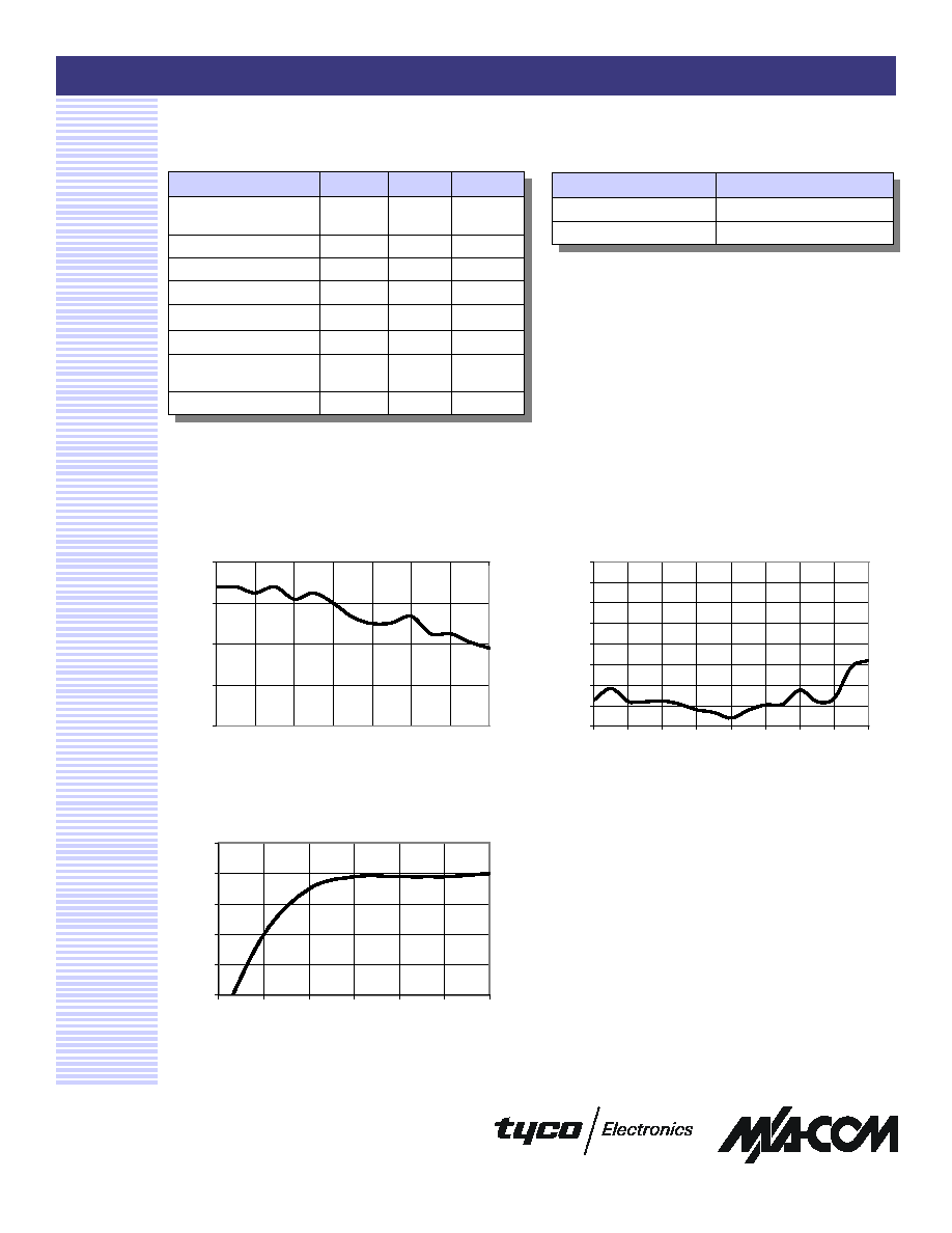
Typical Performance Curves
VSWR
Insertion Loss
Leakage Power at 100 mW
-4.0
-3.0
-2.0
-1.0
0.0
2
4
6
10
12
14
16
18
Frequency (GHz)
Insertion Loss (dB)
1.00
1.25
1.50
1.75
2.00
2.25
2.50
2.75
3.00
2
4
6
8
10
12
14
16
18
Frequency (GHz)
VSWR (Ratio)
0
5
10
15
20
25
0
10
20
30
40
50
60
Power In (dBm)
Power Out (dBm)