Ultra Low Noise pHEMT Dual
Channel Amplifier, 1.710-1.910 GHz
AM40
-
0023
Features
n
0.7 dB Typical Noise Figure
n
14 dB Typical Gain
n
DC Decoupled RF Input and Output
n
Single Bias Configuration
n
SMT Construction
n
Dual Channels for Balanced Designs
n
Unconditionally Stable--No External Matching Circuit
required
Description
M/A-COM's AM40-0023 is a dual-channel, ultra low noise
amplifier in a surface mount package. Very low noise
figure is achieved by using discrete pHEMT devices com-
bined with M/A-COM's glass technology. The
AM40-0023 is designed specifically for use in DCS-1800
and PCS telecommunication applications where less than
1 dB noise figure is required.
CR-5
Electrical Specifications:
Bias Conditions: +7V @ 20 mA Typical (each channel,) T
A
= +25�C, Z
0
= 50 Ohms
Parameter
Test Conditions
Frequency
Units
Min.
Typ.
Max.
Gain
P
IN
= -20 dBm
1.710-1.910 GHz
dB
11
14
--
Gain Flatness
P
IN
= -20 dBm
1.710-1.910 GHz
dB
--
� 1.0
� 1.5
Noise Figure
--
1.710-1.910 GHz
dB
--
0.7
0.9
VSWR Input
P
IN
= -20 dBm
1.710-1.910 GHz
Ratio
--
2.0:1
3.0:1
VSWR Output
P
IN
= -20 dBm
1.710-1.910 GHz
Ratio
--
2.0:1
3.0:1
1 dB Compression
Input Power
1.710-1.910 GHz
dBm
-13
-9
--
Reverse Isolation
--
1.710-1.910 GHz
dB
20
25
--
Input Third Order
Intercept
--
1.710-1.910 GHz
dBm
0
3
--
Absolute Maximum Ratings
1
1. Operation of this device above any one of these
parameters may cause permanent damage.
2. Ambient Temperature (T
A
) = +25�C
Parameter
Absolute Maximum
Max Input Power
2
+15 dBm
Operating Voltage
2
+10.0 V
Operating Temperature
-55�C to +125�C
Storage Temperature
-65�C to +150�C
V 3.00

Ultra Low Noise pHEMT Dual Channel Amplifier, 1.710-1.910 GHz
AM40-0023
Specifications subject to change without notice.
n
North America: Tel. (800) 366-2266
n
Asia/Pacific: Tel.+81-44-844-8296, Fax +81-44-844-8298
n
Europe: Tel. +44 (1344) 869 595, Fax+44 (1344) 300 020
Visit www.macom.com for additional data sheets and product information.
V 3.00
2
Ordering Information
Part Number
Package
AM40-0023
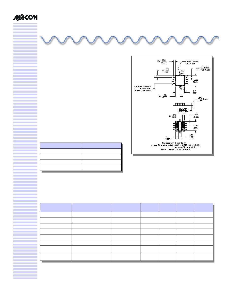
CR-5
Typical Performance Curves
10
12
14
16
18
1700
1750
1800
1850
1900
1950
2000
Frequency (MHz)
Gain (dB)
Gain vs. Frequency
0.0
0.2
0.4
0.6
0.8
1.0
1700
1750
1800
1850
1900
1950
2000
Frequency (MHz)
Noise Figure (dB)
Noise Figure vs. Frequency
Input & Output Return Loss
-20
-15
-10
-5
0
1700
1750
1800
1850
1900
1950
2000
Frequency (MHz)
Return Loss (dB)
RF IN
RF OUT
Functional Schematic (Top View)
GND
1
2
3
4
5
6
7
8
9
10
RF OUT
B
V
DDB
N/C
RF IN
B
GND
RF IN
A
N/C
V
DDA
RF OUT
A