MAAMSS0001_V1
Features
·
Low Noise Figure
·
Low Distortion
·
Surface Mount Package
·
Push-Pull Design Application
·
Single Positive Supply
Description
M/A-COM's MAAMSS0001 is a GaAs
PHEMT MMIC amplifier in a surface mount
SOICN 16 package. The MMIC design
is configured as a pair of cascode PHEMT
amplifiers for broadband performance. It
is designed for integration in a 75-ohm
push-pull low distortion amplifier circuit.
The device is ideally suited for use in
CATV, DBS, and DTV applications where
low noise figure, low distortion and high
linearity are required.
Low Noise CATV Amplifier
50 - 870 MHz
MAAMSS0001
MAAMSS0001
V1
Ordering Information
Part Number
Package
MAAMSS0001
SOICN-16 Plastic Package
MAAMSS0001TR
7 inch, 1000 Piece Reel
MAAMSS0001SMB Sample Test Board
(Includes 5 Samples)
Parameter
Absolute
Maximum
Input Power
+20 dBm
Operating Voltage
+10 volts
Operating Temperature
-40
o
C to +85
o
C
Storage Temperature
-65
o
C to +150
o
C
Absolute Maximum Ratings
1
1. Exceeding any one or combination of these limits
may cause permanent damage to this device.
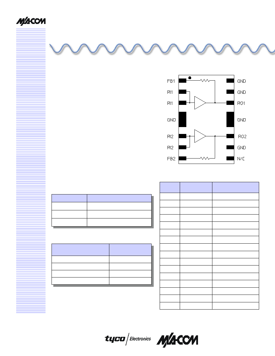
Pin Configuration
Functional Schematic
PIN No.
PIN Name
Description
1
FB1
Feedback 1
2
RI1
RF Input 1
3
RI1
RF Input 1
4
GND
Ground
5
GND
Ground
6
RI2
RF Input 2
7
RI2
RF Input 2
8
FB2
Feedback 2
9
N/C
No Connection
10
GND
Ground
11
RO2
RF Output 2
12
GND
Ground
13
GND
Ground
14
RO1
RF Output 1
15
GND
Ground
16
GND
Ground
M/A-COM Inc. and its affiliates reserve the right to make changes to the product(s)
or information contained herein without notice.
Visit www.macom.com for additional data sheets and product information.
North America: Tel. (800) 366-2266
Asia/Pacific: Tel. +81-44-844-8296, Fax +81-44-844-8298
Europe: Tel. +44 (1908) 574 200, Fax +44 (1908) 574 300
1
Low Noise CATV Amplifier, 50 - 870 MHz
MAAMSS0001
V1
M/A-COM Inc. and its affiliates reserve the right to make changes to the product(s)
or information contained herein without notice.
Visit www.macom.com for additional data sheets and product information.
North America: Tel. (800) 366-2266
Asia/Pacific: Tel. +81-44-844-8296, Fax +81-44-844-8298
Europe: Tel. +44 (1908) 574 200, Fax +44 (1908) 574 300
2
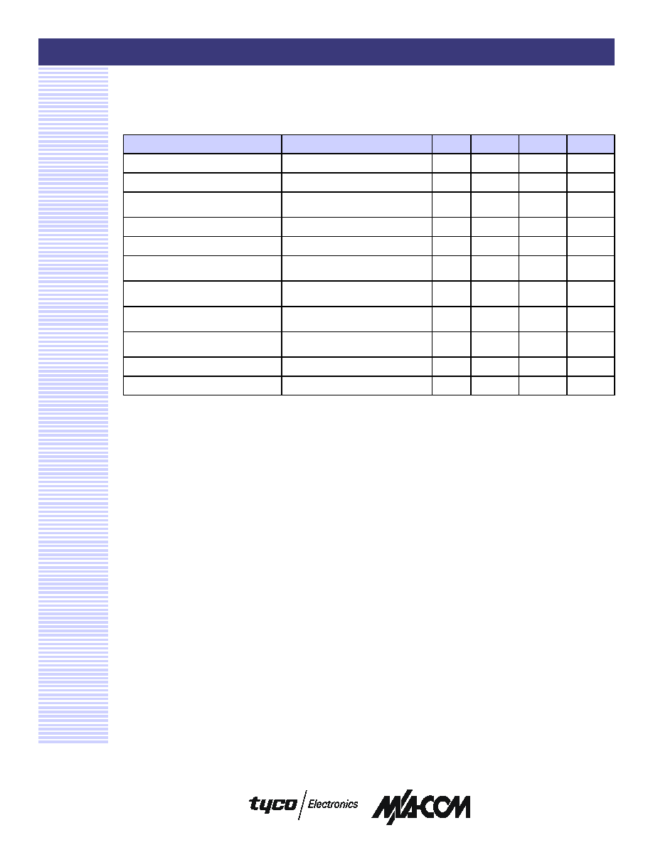
Parameter
Test Conditions
Units
Min.
Typ.
Max.
Gain
dB
11.5
12.0
13.0
Gain Flatness
dB
0.35
Noise Figure
50-150 MHz
150-870 MHz
dB
dB
3.8
2.8
4.0
Input VSWR
ratio
1.4:1
Output VSWR
ratio
1.7:1
IP3
Two tones at 397 & 403 MHz,
+4 dBm output per tone
dBm
33
Composite Triple Beat, CTB
135 Channels, +25 dBmV/
Channel at the output
dBc
-72.5
-70
Composite Second Order, CSO
135 Channels, +25 dBmV/
Channel at the output
dBc
-75
-70
Cross modulation
135 Channels, +25 dBmV/
Channel at the output
dBc
-64
P1dB
400 MHz
dBm
23
I
DD
+ 5 Volts
mA
190
225
Electrical Specifications:
T
A
= 25°C, Freq: 50 - 870 MHz, V
DD
= +5 Volts,
Z
0
= 75 ohms, Test Circuit with M/A-COM Balun ETN1-1-13TR
Handling Procedures
The following precautions should be observed to
avoid damage:
Static Sensitivity
Gallium Arsenide Integrated Circuits are
sensitive to electrostatic discharge (ESD) and
can be damaged by static electricity. Proper
ESD control techniques should be used when
handling these devices.
Low Noise CATV Amplifier, 50 - 870 MHz
MAAMSS0001
V1
M/A-COM Inc. and its affiliates reserve the right to make changes to the product(s)
or information contained herein without notice.
Visit www.macom.com for additional data sheets and product information.
North America: Tel. (800) 366-2266
Asia/Pacific: Tel. +81-44-844-8296, Fax +81-44-844-8298
Europe: Tel. +44 (1908) 574 200, Fax +44 (1908) 574 300
3
11.0
11.5
12.0
12.5
13.0
13.5
14.0
0
250
500
750
1000
-40 °C
+25 °C
+85 °C
Frequency (MHz)
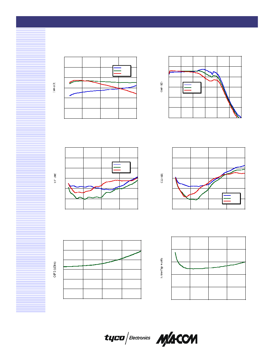
Input Return Loss vs. Frequency over
Temperature
Noise Figure vs. Frequency, 25°C
Gain vs. Frequency to 3 GHz over
Temperature
Gain vs. Frequency over Temperature
OIP3 vs. P
IN
at 400 MHz, 25
°C
Output Return Loss vs. Frequency over
Temperature
Typical Performance Curves
-10
-5
0
5
10
15
20
0
500
1000
1500
2000
2500
3000
-40 °C
+25 °C
+85 °C
Frequency (MHz)
-30
-25
-20
-15
-10
-5
0
0
250
500
750
1000
-40 °C
+25 °C
+85 °C
Frequency (MHz)
-30
-25
-20
-15
-10
-5
0
0
250
500
750
1000
-40 °C
+25 °C
+85 °C
Frequency (MHz)
30
31
32
33
34
35
36
-8
-6
-4
-2
0
P
IN
(dBm)
0
1
2
3
4
5
0
250
500
750
1000
Frequency (MHz)
Low Noise CATV Amplifier, 50 - 870 MHz
MAAMSS0001
V1
M/A-COM Inc. and its affiliates reserve the right to make changes to the product(s)
or information contained herein without notice.
Visit www.macom.com for additional data sheets and product information.
North America: Tel. (800) 366-2266
Asia/Pacific: Tel. +81-44-844-8296, Fax +81-44-844-8298
Europe: Tel. +44 (1908) 574 200, Fax +44 (1908) 574 300
4
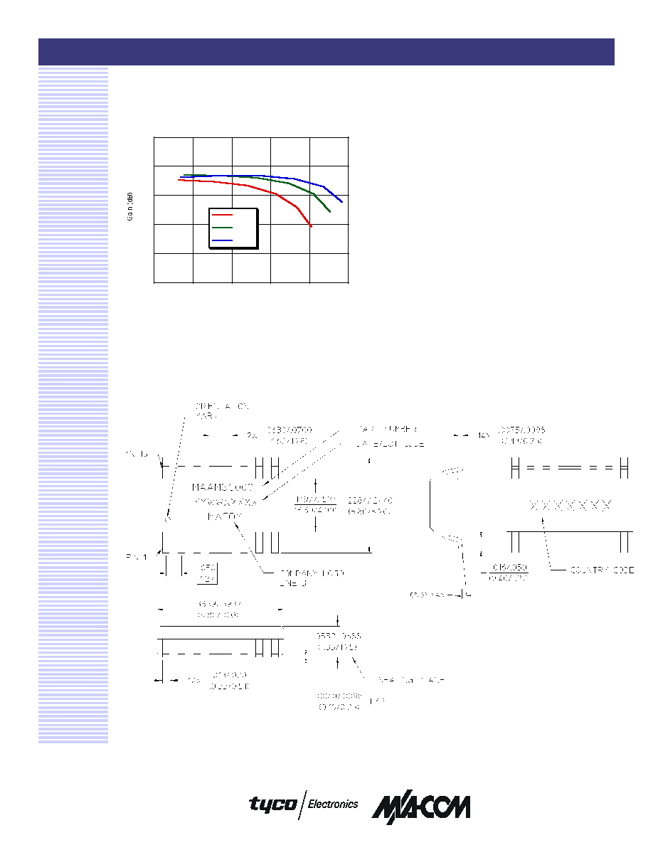
Typical Performance Curves (continued)
Gain vs P
OUT
at 400 MHz vs. Temperature
9
10
11
12
13
14
19
20
21
22
23
24
85 °C
25 °C
-40 °C
P
OUT
(dBm)
SOICN-16
Low Noise CATV Amplifier, 50 - 870 MHz
MAAMSS0001
V1
M/A-COM Inc. and its affiliates reserve the right to make changes to the product(s)
or information contained herein without notice.
Visit www.macom.com for additional data sheets and product information.
North America: Tel. (800) 366-2266
Asia/Pacific: Tel. +81-44-844-8296, Fax +81-44-844-8298
Europe: Tel. +44 (1908) 574 200, Fax +44 (1908) 574 300
5
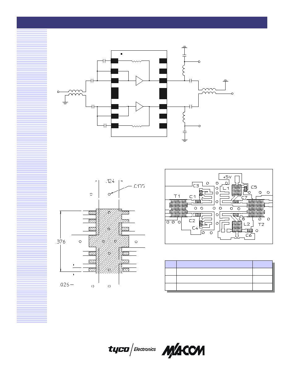
Test Circuit Schematic
The 1:1 baluns, T1 & T2, are M/A-COM part number ETN1-1-13TR.
te
x
t
te
x
t
te
x
t
te
x
t
te
x
t
te
x
t
C6
C8
C7
C4
L2
T2
L1
C5
C3
C1
C2
T1
RF IN
RF OUT
+5V
+5V
te
x
t
te
x
t
te
x
t
te
x
t
te
x
t
te
x
t
te
x
t
te
x
t
Recommended PCB Configuration
with 0.031" thick FR4
Recommended Test Circuit Layout
Qty
Description
8
Capacitor, 0.01uF, 0603, SMT, 10%
(C1-C8)
2
Inductor, 390 nH, 1008, SMT, 10%
(L1, L2)
2
Balun, 1:1, M/A-COM, ETN1-1-13TR, SMT
(T1, T2)
External Circuitry Parts List