
Revision 03-05
Catalog 1308028
Revision 03-06
Please observe the disclaimer.
56
VF28
Powertrain
Systems
Chassis
Systems
Safety
Security
Body
Driver
Information
Convenience
Car Industry
Truck
Industry
Other
Industry
VF28_3d1
Design
Various enclosure options (dust cover,
shrouded/weatherproof cover);
optional mounting bracket
Weight
Approx. 1.2 oz. (34 g) dust cover
model
Nominal voltage
12 V, 24 V
Terminals
2.8 mm dual in-line quick connect
terminals
Accessories
Connectors see page 191
Conditions
All parametric, environmental and
endurance tests are performed
according to EIA Standard RS-407-A
at standard test conditions unless
otherwise noted:
23 ∞C ambient temperature,
20-50% RH, 29.5 ± 1.0" Hg
(998.9 ±33.9 hPa).
Please also refer to the Application
Recommendations in this catalog
for general precautions.
Description
Features
- 30 A continuous contact
rating at 85 ∞C
- Various enclosure options
Typical applications
- Fuel pump
- A/C compressor clutch
- Horn
- Lighting systems
Please contact Tyco Electronics
for relay application support.
Plug-In Relays
Mini 280 Relays
Disclaimer
All technical performance data apply to the relay as such, specific conditions of the individual application are not considered. Please always check the suitability of
the relay for your intended purpose. We do not assume any responsibility or liability for not complying herewith. We recommend to complete our questionnaire and
to request our technical service. Any responsibility for the application of the product remains with the customer only. All specifications are subject to change without
notification. All rights of Tyco are reserved.
Revision 03-05
Catalog 1308028
Revision 03-06
Plug-In Relays
Mini 280 Relays
Please observe the disclaimer.
57
VF28
.453 MAX.
(11.5)
.032 ± .001
(.825 ± .035)
.319
(8.1)
.638
(16.2)
.091
(2.3)
.307
(7.8)
1.004 MAX.
(25.5)
1.12 MAX.
(28.5)
.110
(2.8)
30
86
85
87A
87
1.12 MAX.
(28.5)
ECR2118-M
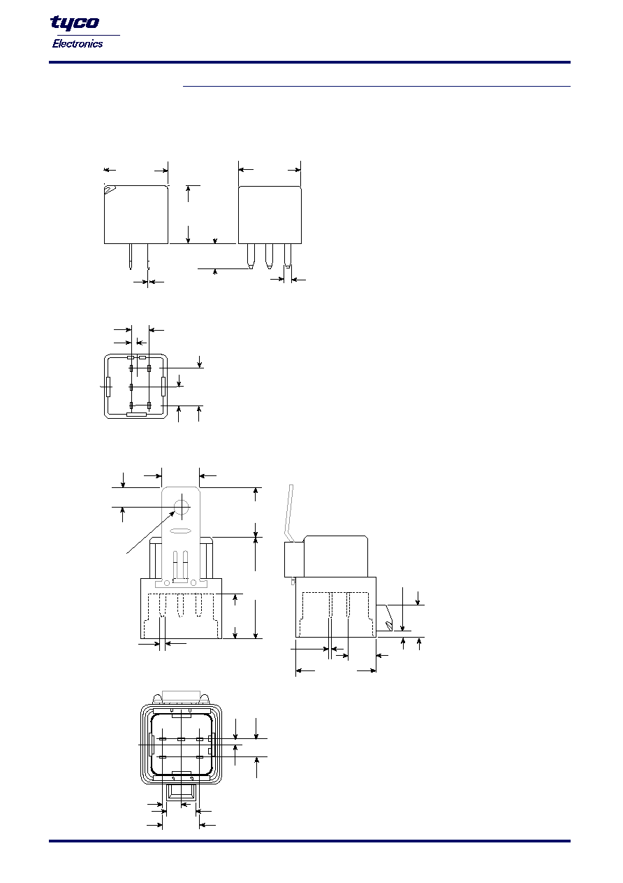
Dimensional drawing
Dust cover with quick connect terminals
VF28-1****
1.8 MAX.
(45.8)
.776
(19.7)
.858
±
0.20
(21.8
±
0.5)
.654
(16.6)
.354
±
.024
(9.0
±
0.6)
.262
6.65
+0.02
-.006
+.005
-.015
( )
.110
(2.80)
.091
(2.3)
.307
(7.8)
.319
(8.1)
.500
±
.016
(12.7
±
0.4)
.638
(16.2)
.110
±
.018
(2.8
±
0.45)
.453
(11.5)
1.425 MAX.
(36.2)
.482 REF.
(12.25)
.032
±
.001
(.825
±
.035)
2 DECIMAL:
±
.004
(
±
0.1)
1 DECIMAL:
±
.006
(
±
0.15)
TOLERANCE UNLESS
OTHERWISE NOTED:
ECR2119-V
Shrouded/weatherproof cover with quick connect terminals
VF28-3**** and VF28-6****
View of the terminals (bottom view)
View of the terminals (bottom view)

Plug-In Relays
Mini 280 Relays
VF28
Please observe the disclaimer.
58
Catalog 1308028
Revision 03-06
Revision 03-05
Contact data
Contact configuration
Circuit symbol
Rated voltage
Rated curent at 85 ∞C
Contact material
Max. switching voltage/power
Max. switching current
1)
On
2)
Off
Min. recommended load
3)
Voltage drop A (initial)
NO contact at 35 A
NC contact at 20 A
Mechanical endurance (without load)
Electrical endurance
(example of resistive load,
further information on request)
Max. switching rate at nominal load
1)
The values apply to a resistive or inductive load with suitable spark suppression and at maximum 13.5 V for 12 V.
2)
For a load current duration of maximum 3 s for a make/break ratio of 1:10.
3)
See chapter Diagnostics in our Application Recommendations on page 18 of this catalog or consult the internet at http://relays.tycoelectronics.com/application.asp
Make contact/
Changeover contact/
Form A
Form C
12 V
12 V
30 A
20/30 A
AgNi0.15
Stationary and NO movable: AgNi0.15, NC movable: A
See load limit curve
NC/NO
120 A
45/120 A
40 A
30/45 A
1 A at 5 V
200 mV max.
200 mV max.
250 mV max.
Typ. 10
7
operations
> 1 x 10
5
operations
> 1 x 10
5
operations
30 A, 14 V
30 A, 14 V
(NO contact)
6 operations per minute (0.1 Hz)
Load limit curve
Pin assignment
1 make contact/
1 changeover contact/
1 form A
1 form C
60
50
40
30
20
10
0.5
1
2
3
4
5
7
10
30
20
Switching Current (A)
Switching Voltage (VDC)
75
40
100 W
200 W
500 W
ECR2115-X
Resistor if used
ECR2159-P
Resistor if used
ECR2160-S
Safe breaking, arc extinguished (normally open contact)
for resistive loads with resistor suppression.

Plug-In Relays
Mini 280 Relays
VF28
Please observe the disclaimer.
59
Catalog 1308028
Revision 03-06
Revision 03-05
Coil data
Available for nominal voltages
12, 24 V
Nominal power consumption of the unsuppressed coil at nominal voltage
1.6 W
Nominal power consumption at nominal voltage with suppression resistor
1.8 W
Test voltage winding/contact
500 VAC
rms
Ambient temperature range
≠ 40 to + 125 ∞C
Operate time at nominal voltage
Typ. 7 ms
Release time at nominal voltage
1)
Typ. 4 ms
1)
For unsuppressed relay coil
N.B.
A low resistive suppression device in parallel to the relay coil increases the release time and reduces
the lifetime caused by increased erosion and/or higher risk of contact tack welding.
Ambient temperature vs. coil voltage for continuous duty
110
100
90
80
70
60
50
90
95
100
105
110
115
120
125
130
135
140
145
150
Applied Coil Voltage (% of Nominal Voltage)
Maximum Allowable Ambient Temperature (
∞
C)
40
120
130
140
ECR2116-6
0 A Contact Load
7 A Contact Load
14 A Contact Load
21 A Contact Load
28 A Contact Load
35 A Contact Load
110
100
90
80
70
60
50
90
95
100
105
110
115
120
125
130
135
140
145
150
Applied Coil Voltage (% of Rated Nominal)
Maximum Allowable Ambient Temperature (
∞
C)
40
120
130
140
0 A Contact Load
6 A Contact Load
12 A Contact Load
18 A Contact Load
24 A Contact Load
30 A Contact Load
ECR2117-E
Assumptions:
1. Still air
2. Nominal coil resistance
3. Maximum mean coil temperature = 180 ∞C
4. Coil temperature rise due to load
= 1.3 ∞C at 7 A
= 3.1 ∞C at 14 A
= 7.2 ∞C at 21 A
= 12.1 ∞C at 28 A
= 19 ∞C at 35 A
5. Thermal resistance and power dissipation based on coil
resistance at 180 ∞C
6. Curves are based on 1.6 W at 23 ∞C
Assumptions:
1. Still air
2. Nominal coil resistance
3. Maximum mean coil temperature = 180 ∞C
4. Coil temperature rise due to load
= 0.8 ∞C at 6 A
= 3.6 ∞C at 12 A
= 6.3 ∞C at 18 A
= 11 ∞C at 24 A
= 16.8 ∞C at 30 A
5. Thermal resistance and power dissipation based on coil
resistance at 180 ∞C
6. Curves are based on 1.6 W at 23 ∞C

Revision 03-05
Catalog 1308028
Revision 03-06
Plug-In Relays
Mini 280 Relays
Please observe the disclaimer.
60
VF28
Ordering information
Part numbers
(see table below for coil data)
Contact
Contact
Enclosure
Terminals
Relay part number
Tyco order number
arrangement
material
VF28-11F14-S01
0-
1393297-1
1 Form A
AgNi0.15
Dust Cover
680 resistor in parallel
VF28-11F24-S01
2-1419084-3
1 Form A
AgSnO2
Dust Cover
680 resistor in parallel
VF28-15F14-S01
0-
1393297-8
1 Form C
AgNi0.15
Dust Cover
680 resistor in parallel
VF28-15F24-S01
1-1393297-3
1 Form C
AgSnO2
Dust Cover
680 resistor in parallel
VF28-61F14-S01
3-1393297-6
1 Form A
AgNi0.15
Weatherproof cover with bracket
680 resistor in parallel
VF28-65F14-S01
4-1393297-5
1 Form C
AgNi0.15
Weatherproof cover with bracket
680 resistor in parallel
Mechanical data
Cover retention
Axial force
150 N (33.8 lbs)
Pull force
200 N (45 lbs)
Push force
200 N (45 lbs)
Terminals
Pull force
100 N (22.5 lbs)
Push force
100 N (22.5 lbs)
Resistance to bending, force applied to front
10 N (2.25 lbs)
1)
Resistance to bending, force applied to side
10 N (2.25 lbs)
1)
Torsion
0.3 Nm
Enclosures
Dust cover
Protects relay from dust. For use in passenger compartment or enclosures
Shrouded/Weatherproof cover
Mates with VC28-1003 connector for application where weather sealing is not required.
1)
Values apply 2 mm from the end of the terminal. When the force is removed, the terminal must not have moved by more than 0.3 mm.
Operating conditions
Temperature range, storage
Refer to
Storage in the "Glossary"
Test
Relevant standard
Testing as per
Dimension
Comments
Vibration resistance
1.27 mm double amplitude
10-40 Hz
Valid for NC contacts.
5 g constant
40-70 Hz
NO contacts are
0.5 mm double amplitude
70-100 Hz
significantly higher
10 g constant
100-500 Hz
Shock resistance
Half sine wave pulse
20 g
No change in the
11 ms
switching state > 1 ms
Jump start
24 VDC for 5 minutes conducting nominal current at 23 ∞C
Drop test
Capable of meeting specifications after 1.0 m (3.28 foot) drop onto concrete
Flammability
UL94-HB or better (meets FMVSS 302)
Internal
External
Overload Current
1)
40.5 A, 1800 s
60 A, 30 s
105 A, 4 s
180 A, 1 s
1)
Current and time are compatibel with circuit protection by a typical 30 A automotive fuse. Relay will make, carry, and break the specified current.
Coil
Must Must
Coil
Rated coil
resistance
operate
release
Allowable overdrive
1)
data for
voltage
+/- 10%
voltage
voltage
voltage (V)
VF28
(V)
()
(V)
(V)
at 23 ∞C
1)
at 85 ∞C
VF28-**F**-***
12 90
7.2
1.2
20.2
15.7
VF28-**H**-***
24
360
14.4
2.4
40.5
31.5
1)
Allowable overdrive is stated with no load applied and minimum coil resistance.
Coil versions
Standard delivery packs (orders in multiples of delivery pack)
Dust cover version:
357 pieces
Weatherproof version with bracket: 110 pieces