Microsoft Word - DS2482-800_ECN.doc
1 of 22
REV: 061804
Note: Some revisions of this device may incorporate deviations from published specifications known as errata. Multiple revisions of any device
may be simultaneously available through various sales channels. For information about device errata, click here:
www.maxim-ic.com/errata
.
GENERAL DESCRIPTION
The DS2482-800 is an I²CTM to 1-Wire
â
bridge device
that interfaces directly to standard (100kHz max) or
fast (400kHz max) I²C masters to perform bi-
directional protocol conversion between the I²C
master and any downstream 1-Wire slave devices.
Relative to any attached 1-Wire slave device, the
DS2482-800 is a 1-Wire master. Internal factory-
trimmed timers relieve the system host processor
from generating time-critical 1-Wire waveforms,
supporting both standard and Overdrive 1-Wire
communication speeds. To optimize 1-Wire
waveform generation, the DS2482-800 performs
slew-rate control on rising and falling 1-Wire edges
and has a programmable feature to mask the fast
presence pulse edge that some 1-Wire slave devices
can generate. Programmable strong pullup features
support 1-Wire power delivery to 1-Wire devices such
as EEPROMs and sensors. The DS2482-800
combines these features with eight independent 1-
Wire I/O channels. The I²C slave address assignment
is controlled by three binary address inputs, resolving
potential conflicts with other I²C slave devices in the
system.
APPLICATIONS
§ Wireless Base Stations
§ Central Office Switches
§ PBXs
§ Rack-Based Servers
§ Medical Clinical Diagnostic Equipment
TYPICAL OPERATING CIRCUIT
(I²C port)
µC
DS2482 800
1-Wire lines
R
t
R
P
IO0
IO1
IO2
IO3
IO4
IO5
IO6
IO7
AD0
AD1
AD2
SDA
SCL
V
CC
1-Wire
Device #1
1-Wire
Device #2
FEATURES
§ I²C Host Interface, Supports 100kHz and 400kHz
I²C Communication Speeds
§ 1-Wire Master I/O with Selectable Active or
Passive 1-Wire Pullup
§ Provides Reset/Presence, 8-Bit, Single-Bit, and
Three-Bit 1-Wire I/O Sequences
§ Eight Channels of Independently Operated
1-Wire I/O
§ Standard and Overdrive 1-Wire Communication
Speeds
§ Slew Controlled 1-Wire Edges
§ Selectable 1-Wire Slave Presence Pulse Falling
Edge Masking to Control Fast Edges on the
1-Wire Line
§ Supports Low-Impedance 1-Wire Strong Pullup
for EEPROMs, Temp Sensors, or Other 1-Wire
Slaves That Have Momentary High Current
Modes
§ Three Address Inputs for I²C Address
Assignment
§ Wide Operating Range: 2.9V to 5.5V, -40°C to
+85°C
§ 16-Pin SO Package (150 mil)
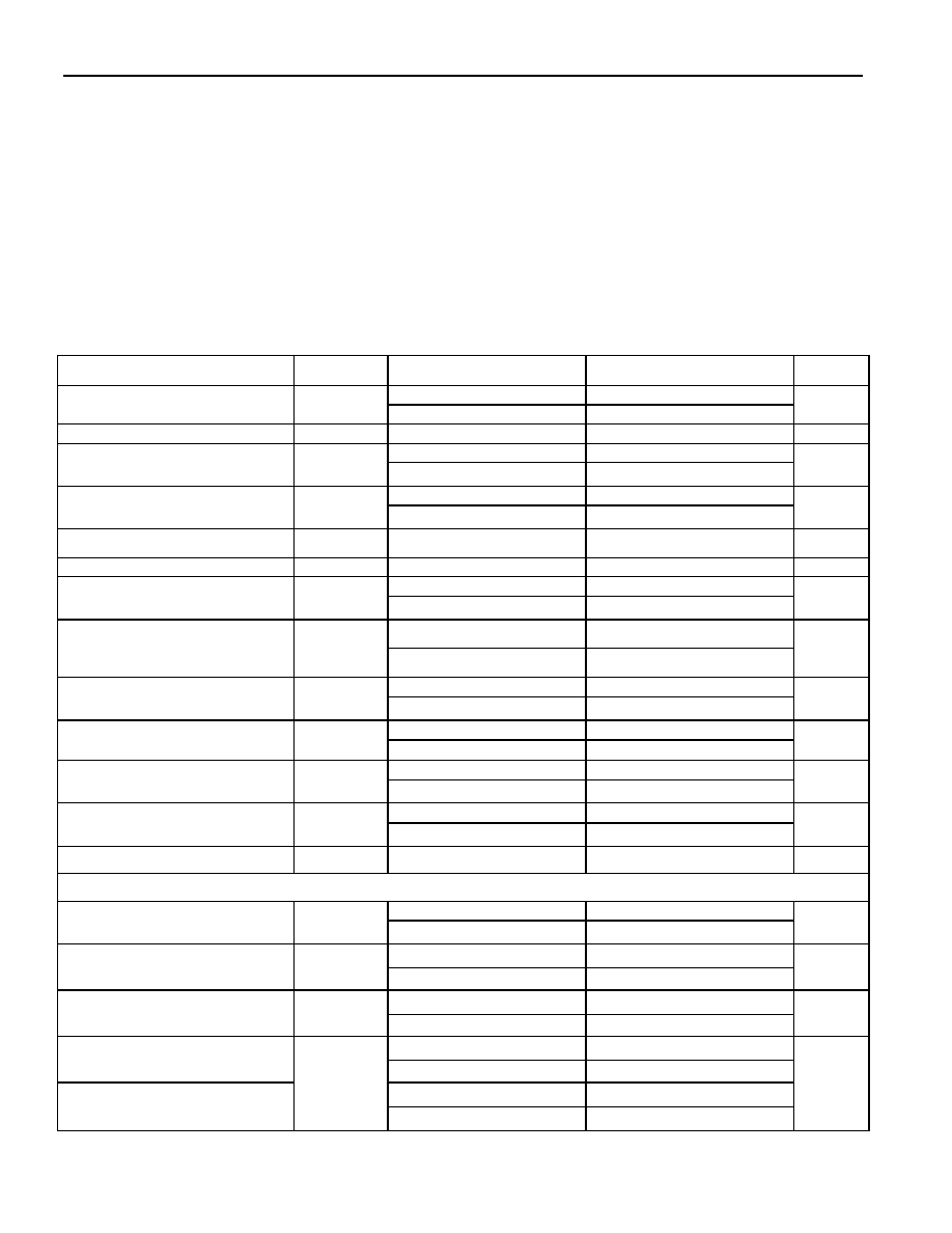
ORDERING INFORMATION
PART TEMP
RANGE
PIN-PACKAGE
DS2482S-800
-40 to +85
°C
16 SO (150 mil )
DS2482S-800/T&R
-40 to +85
°C
16 SO (150 mil )
PIN CONFIGURATION
1
2
3
4
5
6
7
8
16
15
14
13
12
11
10
9
IO2
IO1
IO0
GND
IO4
IO5
IO6
IO7
IO3
SCL
SDA
VDD
NC
AD2
AD1
AD0
DS2482-800
Eight-Channel 1-Wire Master
www.maxim-ic.com
I
2
C is a trademark of Philips Corp. Purchase of I
2
C components from Maxim Integrated Products, Inc., or one of its sublicensed Associated
Companies, conveys a license under the Philips I
2
C Patent Rights to use these components in an I
2
C system, provided that the system
conforms to the I
2
C Standard Specification as defined by Philips.
1-Wire is a registered trademark of Dallas Semiconductor.
DS2482-800: Eight-Channel 1-Wire Master
2 of 22
ABSOLUTE MAXIMUM RATINGS
Voltage Range on Any Pin Relative to Ground
-0.5V, +6V
Maximum Current Into Any Pin
±20mA
Operating Temperature Range
-40°C to +85°C
Junction Temperature
+150°C
Storage Temperature Range
-55°C to +125°C
Soldering Temperature
See IPC/JEDEC J-STD-020A
Stresses beyond those listed under "Absolute Maximum Ratings" may cause permanent damage to the device. These are stress ratings only,
and functional operation of the device at these or any other conditions beyond those indicated in the operational sections of the specifications is
not implied. Exposure to the absolute maximum rating conditions for extended periods may affect device.
ELECTRICAL CHARACTERISTICS
(V
CC
= 2.9V to 5.5V, T
A
= -40°C to +85°C.)
PARAMETER SYMBOL
CONDITIONS
MIN
TYP
MAX
UNITS
3.3V 2.9
3.3
3.7
Supply Voltage
V
CC
5V 4.5
5.0
5.5
V
Operating Current
I
CC
(Note
1)
0.75 mA
3.3V (Notes 2, 3)
1.9
1-Wire Input High
V
IH1
5V (Notes 2, 3)
3.4
V
3.3V (Notes 2, 3)
0.75
1-Wire Input Low
V
IL1
5V (Notes 2, 3)
1.0
V
1-Wire Weak Pullup Resistor
R
WPU
(Note
4)
800 1675 W
1-Wire Output Low
V
OL1
At 4mA load
0.4
V
Standard (Notes 4, 5)
2.3
2.5
2.7
Active Pullup On Time
t
APUOT
Overdrive (Notes 4, 5)
0.4
0.5
0.6
µs
V
CC
³ 3.2V, 1.5mA load
0.3
Strong Pullup Voltage Drop
DV
STRPU
V
CC
³ 5.2V, 3mA load
0.5
V
Standard (3.3V
±5%)
1 4.2
3.3V Pulldown Slew Rate
(Note 6)
PD
SRC
Overdrive (3.3V
±5%)
5 22.1
V/µs
Standard (5.0V
±5%)
2 6.5
5V Pulldown Slew Rate
(Note 6)
PD
SRC
Overdrive (5.0V
±5%)
10 40
V/µs
Standard (3.3V
±5%)
0.8 4
3.3V Pullup Slew Rate (Note 6)
PU
SRC
Overdrive (3.3V
±5%)
1.3 6
V/µs
Standard (5.0V
±5%)
2.7 20
5V Pullup Slew Rate (Note 6)
PU
SRC
Overdrive (5.0V
±5%)
3.4 31
V/µs
Power-On Reset Trip Point
V
POR
2.2
V
1-Wire TIMING (Note 16) See Figures 3, 5, 6, and 7
Standard
7.6
8
8.4
Write 1/Read Low Time
t
W1L
Overdrive 0.9
1
1.1
µs
Standard 13.3
14
15
Read Sample Time
t
MSR
Overdrive 1.4
1.5
1.8
µs
Standard 65.8
69.3
72.8
1-Wire Time Slot
t
slot
Overdrive 9.9
10.5
11.0
µs
3.3V to 0V (Note 5)
0.6
2.6
Fall Time High-to-Low at
Standard Speed (Note 6)
5.5V to 0V (Note 5)
0.7
2.2
3.3V to 0V (Note 5)
0.1
0.5
Fall Time High-to-Low at
Overdrive Speed (Note 6)
t
F1
5.5V to 0V (Note 5)
0.1
0.4
µs
DS2482-800: Eight-Channel 1-Wire Master
3 of 22
PARAMETER SYMBOL
CONDITIONS
MIN
TYP
MAX
UNITS
Standard 60
64
68
Write 0 Low Time
t
W0L
Overdrive 7.1
7.5
7.9
µs
Standard 5.0
5.3
5.6
Write 0 Recovery Time
t
REC0
Overdrive 2.8
3.0
3.2
µs
Standard 570
600
630
Reset Low Time
t
RSTL
Overdrive 68.4
72
75.6
µs
Standard 66.5
70
73.5
Presence-Detect Sample Time
t
MSP
Overdrive 7.1
7.5
7.9
µs
Standard 7.6
8
8.4
Sampling for Short and
Interrupt
t
SI
Overdrive 0.7
0.75
0.8
µs
Standard 554.8
584
613.2
Reset High Time
t
RSTH
Overdrive 70.3
74
77.7
µs
Presence Pulse Mask Start
t
ppm1
(Note
7)
9.5 10 10.5 µs
Presence Pulse Mask Stop
t
ppm2
(Note
7)
57 60 63
µs
I²C-Pins (Note 8) See Figure 10
V
CC
= 2.9V to 3.7V
0.25 ×
V
CC
LOW Level Input Voltage
V
IL
V
CC
= 4.5V to 5.5V
-0.5
0.22 ×
V
CC
V
HIGH Level Input Voltage
V
IH
0.7 ×
V
CC
V
CC
+
0.5V
V
Hysteresis of Schmitt Trigger
Inputs
V
hys
0.05 ×
V
CC
V
LOW Level Output Voltage at
3mA Sink Current
V
OL
0.4 V
Output Fall Time from V
Ihmin
to
V
ILmax
with a Bus Capacitance
from 10pF to 400pF
t
of
60 250 ns
Pulse Width of Spikes that are
Suppressed by the Input Filter
t
SP
SDA and SCL pins only
50
ns
Input Current Each I/O Pin with
an Input Voltage Between
0.1V
CCmax
and 0.9V
CCmax
I
i
(Notes
9,
10)
-10 10 µA
Input Capacitance
C
i
(Note
9)
10 pF
SCL Clock Frequency
f
SCL
0
400 kHz
Hold Time (Repeated) START
Condition. After this Period, the
First Clock Pulse is Generated.
t
HD:STA
0.6
µs
LOW Period of the SCL Clock
t
LOW
1.3
µs
HIGH Period of the SCL Clock
t
HIGH
0.6
µs
Setup Time for a Repeated
START Condition
t
SU:STA
0.6
µs
Data Hold Time
t
HD:DAT
(Notes 11, 12)
0.9
µs
Data Setup Time
t
SU:DAT
(Note
13)
250
ns
Setup Time for STOP Condition
t
SU:STO
0.6
µs
Bus Free Time Between a
STOP and START Condition
t
BUF
1.3
µs
Capacitive Load for Each Bus
Line
C
b
(Note
14)
400 pF
Oscillator Warm-Up Time
t
OSCWUP
(Note
15)
100
µs

DS2482-800: Eight-Channel 1-Wire Master
4 of 22
PIN DESCRIPTION
Note 1:
Operating current with 1-Wire write byte sequence followed by continuous Read of Status Register at
400KHz in Overdrive.
Note 2:
With standard speed the total capacitive load of the 1-Wire bus should not exceed 1nF, otherwise the
passive pullup on threshold V
IL1
may not be reached in the available time. With Overdrive speed the
capacitive load on the 1-Wire bus must not exceed 300pF.
Note 3:
Active pullup guaranteed to turn on between V
IL1MAX
and V
IH1MIN
.
Note 4:
Active or resistive pullup choice is configurable.
Note 5:
Fall time high to low (t
F1
) is derived from PD
SRC,
referenced from 0.9 × V
CC
to 0.1 × V
CC
.
Note 6:
These values apply at full load, i. e., 1nF at standard speed and 0.3nF at Overdrive speed. For
reduced load, the pulldown slew rate is slightly faster.
Note 7:
Presence pulse masking only applies to standard speed.
Note 8:
All I²C timing values are referred to V
IHmin
and V
ILmax
levels.
Note 9:
Applies to SDA, SCL, and AD0, AD1, AD2.
Note 10:
I/O pins of the DS2482 do not obstruct the SDA and SCL lines if V
CC
is switched off.
Note 11:
The DS2482 provides a hold time of at least 300ns for the SDA signal (referred to the V
IHmin
of the SCL
signal) to bridge the undefined region of the falling edge of SCL.
Note 12:
The maximum t
HD
:
DAT
has only to be met if the device does not stretch the LOW period (t
LOW
) of the
SCL signal.
Note 13:
A Fast-mode I²C-bus device can be used in a standard-mode I²C-bus system, but the requirement
t
SU
:
DAT
³250ns must then be met. This is automatically the case if the device does not stretch the LOW
period of the SCL signal. If such a device does stretch the LOW period of the SCL signal, it must
output the next data bit to the SDA line tr max + t
SU
:
DAT
= 1000 + 250 = 1250ns (according to the
standard-mode I²C-bus specification) before the SCL line is released.
Note 14:
C
B
= total capacitance of one bus line in pF. If mixed with HS-mode devices, faster fall-times according
to I²C-Bus Specification v2.1 are allowed.
Note 15:
I²C communication should not take place for the max t
OSCWUP
time following a power-on reset.
Note 16:
Except for t
F1
, all 1-Wire timing specifications and t
APUOT
are derived from the same timing circuit.
Therefore, if one of these parameters is found to be off the typical value, it is safe to assume that all of
these parameters deviate from their typical value in the same direction and by the same degree.
PIN NAME
FUNCTION
1
IO3
IO Driver for 1-Wire Line #3
2
SCL
I²C Serial Clock Input; must be tied to VCC through a pullup resistor.
3
SDA
I²C Serial Data Input/Output; must be tied to VCC through a pullup resistor.
4
VCC
Power Supply Input
5 NC
Not
Connected
6 AD2
7 AD1
8 AD0
I²C Address Inputs; must be tied to VCC or GND. These inputs determine the I²C slave
address of the device, see Figure 9.
9
IO7
IO Driver for 1-Wire Line #7
10
IO6
IO Driver for 1-Wire Line #6
11
IO5
IO Driver for 1-Wire Line #5
12
IO4
IO Driver for 1-Wire Line #4
13
GND
Ground Reference
14
IO0
IO Driver for 1-Wire Line #0
15
IO1
IO Driver for 1-Wire Line #1
16
IO2
IO Driver for 1-Wire Line #2
DS2482-800: Eight-Channel 1-Wire Master
5 of 22
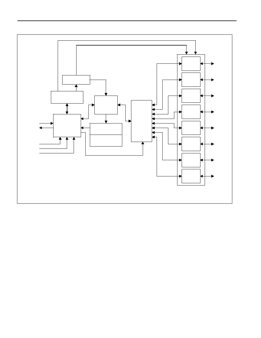
Figure 1. Block Diagram
I²C
Interface
Controller
SDA
SCL
Config
Register
I/O
Controller
Status
Register
Line
XCVR
Channel
Select
Line
XCVR
Line
XCVR
Line
XCVR
Line
XCVR
Line
XCVR
Line
XCVR
Line
XCVR
AD0
AD1
AD2
IO0
IO1
IO2
IO3
IO4
IO5
IO6
IO7
Read Data
Register
T-Time OSC
DETAILED DESCRIPTION
The DS2482-800 is a self-timed 8-channel 1-Wire master, which supports advanced 1-Wire waveform features
including standard and Overdrive speeds, active pullup, strong pullup for power delivery, and presence pulse
masking. Once supplied with command and data, the I/O controller of the DS2482 performs time-critical 1-Wire
communication functions such as reset/presence detect cycle, read-byte, write-byte, single-bit R/W and triplet for
ROM Search, without requiring interaction with the host processor. The host obtains feedback (completion of a 1-
Wire function, presence pulse, 1-Wire short, search direction taken) through the Status Register and data through
the Read Data register. The DS2482 communicates with a host processor through its I²C bus interface in standard-
mode or in fast-mode. The logic state of three address pins (2 address pins with the 1-channel version) determines
the I²C slave address of the DS2482, allowing up to 8 devices operating on the same bus segment without
requiring a hub.
DEVICE REGISTERS
The DS2482 has four registers that the I²C host can read: Channel Selection, Configuration, Status, and Read
Data. These registers are addressed by a read pointer. The position of the read pointer, i.e., the register that the
host will read in a subsequent read access, is defined by the instruction that the has DS2482 executed last. The
host has read and write access to the Channel Selection and Configuration Registers to select one of several 1-
Wire channels and to enable certain 1-Wire features.