
1N957
THRU
1N978
0.5W Silicon Planar
Zener Diodes
)HDWXUHV
∑
Zener Voltage 6.8V to 51V
∑
Silicon Planar Power Zener Diodes
∑
Standards zener voltage tolerance is ±20%, Add suffix "A" for
±10% tolerance and suffix "B" for ±5% tolerance, non standards
and higher zener voltage upon request
0D[LPXP5DWLQJV
Symbol
Value
Units
Zener Current See Table 1
Power Dissipation
@ T
A
=25
o
C
P
tot
500 mW
Junction Temperature T
J
175
o
C
Storage Temperature
Range
T
STG
-65 to 175
o
C
(OHFWULFDO &KDUDFWHULVWLFV #
∞
& 8QOHVV 2WKHUZLVH 6SHFLILHG
Symbol
Maximum
Unit
Thermal resistance R
-$
300
o
C/W
Forward Voltage
@ I
F
=200mA
V
F
1.5 V
NOTE:
Valid provided that a distance of 8mm from case are kept at
ambient temperature
0HFKDQLFDO'DWD
∑
Case: DO-35 glass case
∑
Polarity: Color band denotes cathode end
∑
Weight: Approx. 0.13 gram
omponents
21201 Itasca Street Chatsworth
!"#
$
% !"#
M C C
www.
mccsemi
.com
A
B
C
D
D
Cathode
Mark
DIMENSIONS
INCHES
MM
DIM
MIN
MAX
MIN
MAX
NOTE
A
---
.166
---
4.2
B
---
.079
---
2.00
C
---
.020
---
.52
D
1.000
---
25.40
---
DO-35
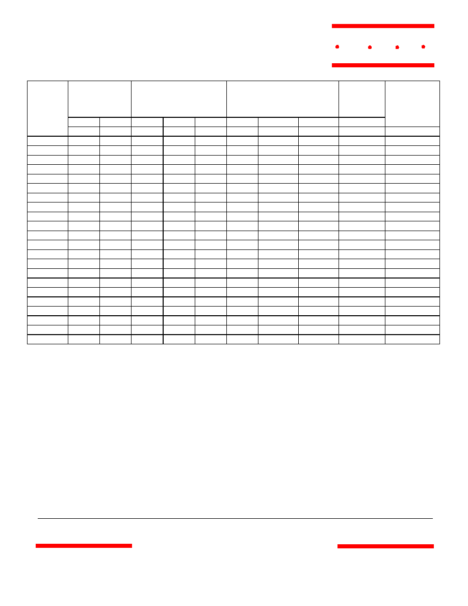
ZENER
VOLTAGE
3)
@TEST
CURRENT
MAXIMUM ZENER
IMPEDANCE
1)
MAXIMUM REVERSE
LEAKAGE CURRENT
TEST-VOLTAGE
MAXIMUM
ZENER
CURRENT
V
Z
I
ZT
Z
ZT
Z
ZK
I
ZK
I
R
2)
Suffix A
Suffix B
I
ZM
2)
TYPICAL
TEMP.
COEFFICIENT
MCC
PART
NUMBER
V mA
mA
A V V mA %/
:
1N957 6.8 18.5 4.5 700 1.0 150 4.9 5.2 47 0.050
1N958 7.5 16.5 5.5 700 0.5 75 5.4 5.7 42 0.058
1N959 8.2 15 5.5 700 0.5 50 5.9 6.2 38 0.062
1N960 9.1 14 5.5 700 0.5 10 6.6 6.9 35 0.068
1N961 10 12.5 5.5 700 0.25 5 7.2 7.6 32 0.075
1N962 11 11.5 5 700 0.25 5 8.0 8.4 28 0.076
1N963 12 10.5 11.5 700 0.25 5 8.6 9.1 26 0.077
1N964 13 9.5 13 700 0.25 5 9.4 9.9 24 0.079
1N965 15 8.5 16 700 0.25 5 10.8 11.4 21 0.082
1N966 16 7.8 17 700 0.25 5 11.5 12.2 19 0.083
1N967 18 7.0 21 750 0.25 5 13.0 13.7 17 0.085
1N968 20 6.2 25 750 0.25 5 14.4 15.2 15 0.086
1N969 22 5.6 29 750 0.25 5 15.8 16.7 14 0.087
1N970 24 5.2 33 750 0.25 5 17.3 18.2 14 0.088
1N971 27 4.6 41 750 0.25 5 19.4 20.6 11 0.090
1N972 30 4.2 49 1000 0.25 5 21.6 22.8 10 0.091
1N973 33 3.8 58 1000 0.25 5 23.8 25.1 9.0 0.092
1N974 36 3.4 70 1000 0.25 5 25.9 27.4 8.5 0.093
1N975 39 3.2 80 1000 0.25 5 28.1 29.7 7.8 0.094
1N976 43 3.0 93 1500 0.25 5 31.0 32.7 7.0 0.095
1N977 47 2.7 105 1500 0.25 5 33.8 35.8 6.4 0.095
1N978 51 2.5 125 1500 0.25 5 36.7 38.8 5.9 0.096
Note:
1)
The Zener impedance is derived from the 1kHz AC voltage which results when an AC current having an RMS
value equal to 10% of the Zener current (I
ZT
) is superimposed on I
ZT
Zener impedance is measured at two points
to insure a sharp knee on the breakdown curve and to eliminate unstable units.
2)
Valid provided that leads are kept at ambient temperature at a distance of 8mm from case.
3)
Measured with device junction in thermal equilibrium.
www.
mccsemi
.com
M C C
1N957 thru 1N978