SS22
THRU
SS210
2 Amp Schottky
Rectifier
20 to 100 Volts
Features
∑
Schottky Barrier Rectifier
∑
Guard Ring Protection
∑
Low Forward Voltage
∑
Reverse Energy Tested
∑
High Current Capability
∑
Extremely Low Thermal Resistance
Maximum Ratings
∑
Operating Temperature: -55
∞
C to +125
∞
C
∑
Storage Temperature: -55
∞
C to +150
∞
C
∑
Maximum Thermal Resistance; 15
∞
C/W Junction To Lead
MCC
Catalog
Number
Device
Marking
Maximum
Recurrent
Peak Reverse
Voltage
Maximum
RMS
Voltage
Maximum
DC
Blocking
Voltage
SS22 SS22 20V 14V 20V
SS23 SS23 30V 21V 30V
SS24 SS24 40V 28V 40V
SS25 SS25 50V 35V 50V
SS26 SS26 60V 42V 60V
SS28 SS28 80V 56V 80V
SS210 SS210 100V 70V 100V
Electrical Characteristics @ 25
∞
C Unless Otherwise Specified
Average Forward
Current
I
F(AV)
2.0A T
J
= 100
∞
C
0.5mA
Maximum DC Reverse
Current At Rated DC
Blocking Voltage
I
R
T
J
= 25
∞
C
Typical Junction
Capacitance
SS22
SS23-SS210
C
J
230pF
50pF
Measured at
1.0MHz, V
R
=4.0V
*Pulse test: Pulse width 300
µ
sec, Duty cycle 2%
Maximum
Instantaneous
Forward Voltage
SS22-SS24
SS25-SS26
SS28-SS210
V
F
.55V
.70V
.85V
I
FM
= 2.0A;
T
J
= 25
∞
C*
www.
mccsemi
.com
Peak Forward Surge
Current
I
FSM
50A 8.3ms, half sine
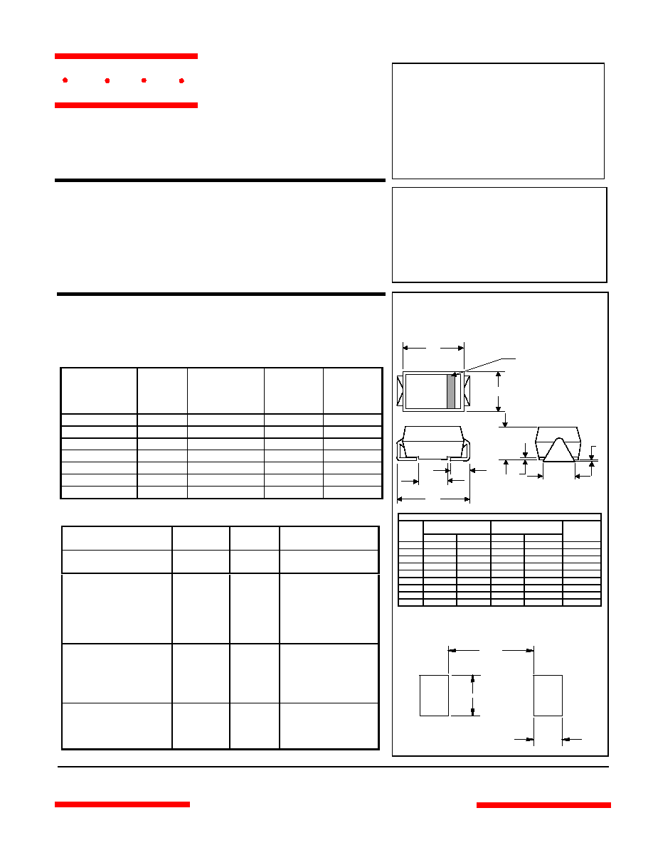
DO-214AC
(SMAJ) (High Profile)
H
J
E
F
G
A
B
D
C
Cathode Band
0.070"
0.090"
0.085"
SUGGESTED SOLDER
PAD LAYOUT
DIMENSIONS
INCHES
MM
DIM
MIN
MAX
MIN
MAX
NOTE
A .078 .116 1.98 2.95
B .067 .089 1.70 2.25
C .002 .008 .05 .20
D --- .02 --- .51
E .035 .055 .89 1.40
F .065 .096 1.65 2.45
G .205 .224 5.21 5.69
H .160 .180 4.06 4.57
J .100 .112 2.57 2.84
omponents
21201 Itasca Street Chatsworth
!"#
$
% !"#
M C C
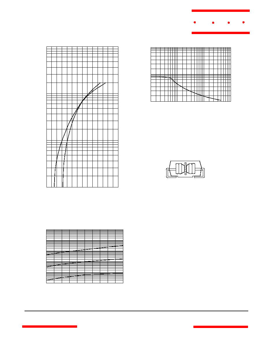
SS22
Figure 1
Typical Forward Characteristics
Instantaneous Forward Current - Amperes
versus
Instantaneous Forward Voltage - Volts
0
.2
.4
.6
.8
1.0
1.2
1.4
.1
.2
.4
.6
.8
1.0
2.0
4.0
6.0
8.0
10
20
40
60
80
100
Volts
Amps
Figure 2
Typical Reverse Characteristics
0
5
10
15 20
25 30
35
40
45
50
.001
.1
1
10
100
1000
125
∞
C
75
∞
C
25
∞
C
Typical Reverse Current - mA
versus
Reverse Voltage - Volts
mA
Volts
25
∞
C
125
∞
C
Figure 3
Typical Junction Capacitance
Junction Capacitance - pF
versus
Reverse Voltage - Volts
Volts
pF
0.
0.5
1.0
5.0
10
50
100
100
200
400
600
1000
2000
4000
6000
10000
Figure 4
New SMA Assembly
Round Lead
Process
M C C
www.
mccsemi
.com
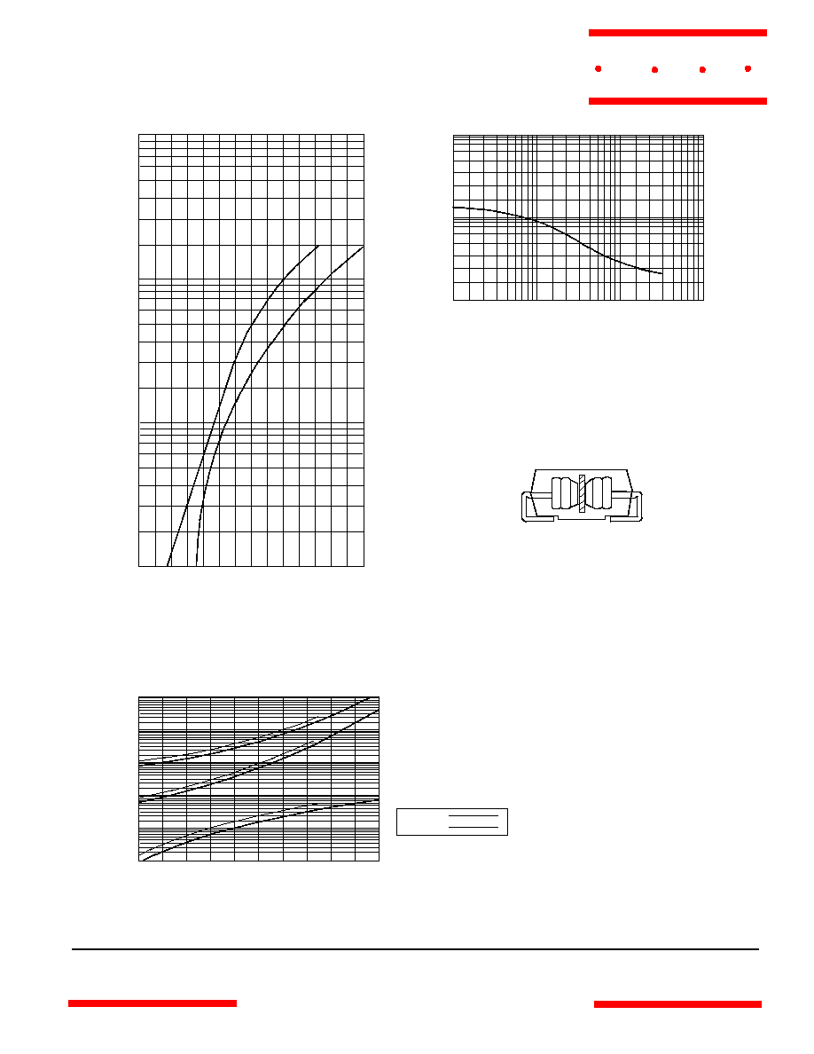
SS23 thru SS210
Instantaneous Forward Current - Amperes
versus
Instantaneous Forward Voltage - Volts
Figure 1
Typical Forward Characteristics
0
.2
.4
.6
.8
1.0
1.2
1.4
.1
.2
.4
.6
.8
1.0
2.0
4.0
6.0
8.0
10
20
40
60
80
100
25
∞
C
Volts
Amps
Figure 2
Typical Reverse Characteristics
0
4
8
12
16
20 24
28
32
36
40
.001
.01
.1
1
10
100
25
∞
C
Typical Reverse Current - mA
versus
Reverse Voltage - Volts
mA
Volts
125
∞
C
Figure 3
Typical Junction Capacitance
Junction Capacitance - pF
versus
Reverse Voltage - Volts
Volts
pF
0.
0.5
1.0
5.0
10
50
100
10
20
40
60
100
200
400
600
1000
75
∞
C
125
∞
C
SS23
SS24
Figure 4
New SMA Assembly
Round Lead
Process
M C C
www.
mccsemi
.com