
UPS120
THRU
UPS140
1 Amp Schottky
Rectifier
20 to 40 Volts
Features
Maximum Ratings
Electrical Characteristics @ 25
∞
C Unless Otherwise Specified
Average Forward
Current
I
F(AV)
1.0A T
J
=
135∞
C
Peak Forward Surge
Current
I
FSM
50A 8.3ms, half sine
Maximum
Instantaneous
Forward Voltage
V
F
.45 V I
FM
= 1.0A;
T
J
= 25
∞
C*
Maximum DC
Reverse Current At
Rated DC Blocking
Voltage
I
R
T
J
= 25
∞
C
T
J
= 85
∞
C
∑
Maximum Thermal Resistance; 10
∞
C/W Junction To Bottom
MCC
Catalog
Number
Device
Marking
Maximum
Recurrent
Peak Reverse
Voltage
Maximum
RMS
Voltage
Maximum
DC
Blocking
Voltage
UPS120 BCF 20V 14V 20V
UPS130 BCG 30V 21V 30V
UPS140 BCJ 40V 28V 40V
www.
mccsemi
.com
A
E
G
TAB 1 CATHODE
TAB 2 ANODE
DO-216AA
POWERMITE
(
)
)
)
)
C
D
F
J
K
L
B
H
∑
High Power Surface Mount Package
∑
Guard Ring Protection
∑
Low Forward Voltage
∑
Integral Heat Sink/Locking Tabs
∑
Compatible with Automatic Insertion Equipment
∑
Maximum Thermal Resistance; 23∞C/W Junction To Tab
∑
Operating Temperature: -55
∞
C to +150
∞
C
∑
Storage Temperature: -55
∞
C to +150
∞
C
*Pulse test: Pulse width 200
µ
sec, Duty cycle 2%
UPS120
UPS130 .55 V
UPS140 .55 V
UPS120 .40/25mA
UPS130 .41/11mA
UPS140 .50/25mA
V
R
= 20V
V
R
= 40 V
V
R
= 30 V
INCHES MM
DIM MIN MAX MIN MAX NOTE
DIMENSIONS
A .143 .153 3.63 3.89
B .070 .080 1.78 2.03
C .070 .080 1.78 2.03
D .087 .097 2.21 2.46
E .029 .039 0.74 0.99
F .051 .061 1.30 1.55
G ----- .026 ----- 0.66
H .035 .045 0.89 1.14
J .021 .031 0.53 0.79
K ----- .025 ----- 0.64
L ----- .006 ----- 0.15
omponents
21201 Itasca Street Chatsworth
!"#
$
% !"#
M C C
NOTE:
package is patental by microsemi corp.
POWERMITE

UPS120 thru UPS140
Average Forward Rectified Current - Amperes
versus
Ambient Temperature -
∞
C
Figure 2
Forward Derating Curve
0
150
25
50
75
100
0
.2
.4
.6
Single Phase, Half Wave
60Hz Resistive or Inductive Load
Amps
∞
C
125
.8
1.0
1.2
Instantaneous Forward Current - Amperes
versus
Instantaneous Forward Voltage - Volts
Figure 1
Typical Forward Characteristics
4
6
20
10
Amps
.2
.4
.6
.8
1.0
1.2
.01
.02
.04
.06
.1
.2
.4
.6
1
2
25
∞
C
Volts
Figure 3
Junction Capacitance
.1
.2
1
.4
2
10
20
40
4
100 200
1
2
6
10
20
100
Junction Capacitance - pF
versus
Reverse Voltage - Volts
pF
Volts
60
40
4
400
1000
T
J
=25
∞
C
M C C
www.
mccsemi
.com
UPS120 thru UPS140
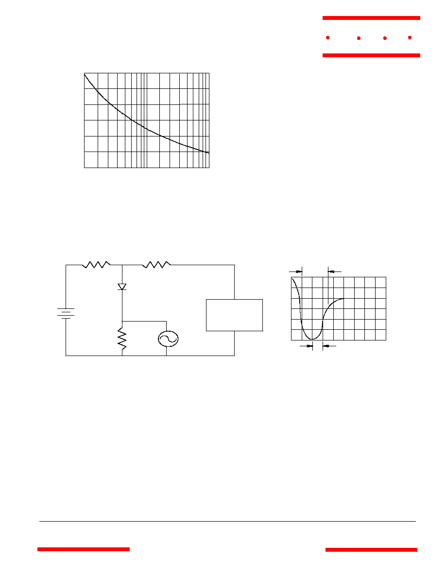
t
rr
+0.5A
0
-0.25
-1.0
1cm
Set Time Base for 20/100ns/cm
25Vdc
1
50
10
Oscilloscope
Note 1
Pulse
Generator
Note 2
Notes:
1. Rise Time = 7ns max.
Input impedance = 1 megohm, 22pF
2. Rise Time = 10ns max.
Source impedance = 50 ohms
3. Resistors are non-inductive
Figure 6
Reverse Recovery Time Characteristic And Test Circuit Diagram
1
100
4
0
5
10
20
8
Figure 4
Peak Forward Surge Current
Peak Forward Surge Current - Amperes
versus
Number Of Cycles At 60Hz - Cycles
Amps
Cycles
2
6
10 20
60 80
40
30
40
50
M C C
www.
mccsemi
.com