 | –≠–ª–µ–∫—Ç—Ä–æ–Ω–Ω—ã–π –∫–æ–º–ø–æ–Ω–µ–Ω—Ç: 2GT-22 | –°–∫–∞—á–∞—Ç—å:  PDF PDF  ZIP ZIP |

ATTENUATORS, PIN DIODE SERIES GT, 1GT,
0.25≠18 G H
z
2GT, GA
GENERAL INFORM
A
TION
KDI/Triangle Pin Diode attenuators continuously change the amplitude of
a microwave signal by applying a varying DC current, voltage, or digital
signal, depending upon the Model type selected. The basic current con-
trolled models do not have thermal compensation included, the voltage
controlled & digital models have linearization and/or temperature com-
pensation options.
A matched configuration of diodes keeps the VSWR low through all
values of attenuation and frequency.
Linearization is provided in some models, which produces an output
signal that is linearly proportional to the control voltage.
Temperature compensation is also provided in some models, over either
the ≠55 to +85 degree C range, 10≠40 degree C range, or 0-70 degree C
range depending upon the Model type selected. Digitally controlled ana-
log attenuators, Model series "GA", require an TTL binary logic input.
Standard units in the GA series have an 8 bit input producing 256 dis-
crete values of attenuation. Optional 10≠12 bit logic is readily available
simply by specifying in the model number with a dash number.
Accuracy
Model
Input
Chart
Input
No.*
Control
No.
Control
Input Fixed
GT-( )
Current
A, B
0≠10MA
None
1-GT-( )
VOLTAGE 10 TO 40 C
A, B
0≠10VDC
+ & ≠ 15VDC @50 MA MAX
1-GT-( )TT
VOLTAGE-TEMP COMP ≠55 TO +85 C
C
0≠10VDC
+ & ≠ 15VDC @50 MA MAX
1-GT-( )TR
VOLTAGE-TEMP COMP 0 TO 70 C
D
0≠10VDC
+ & ≠ 15VDC @50 MA MAX
2-GT-( )
VOLTAGE- LINEARIZED 10 TO 40 C
A, B
0≠10VDC
+ & ≠ 15VDC @50 MA MAX
2-GT-( )TT
VOLTAGE-LINEARIZED TEMP COMP ≠55 TO +85 C
C
0≠10VDC
+ & ≠ 15VDC @50 MA MAX
2-GT-( )TR
VOLTAGE-LINEARIZED TEMP COMP 0 TO 70 C
D
0≠10VDC
+ & ≠ 15VDC @50 MA MAX
GA-(
)
DIGITAL-TTL 10 TO 40 C
A, B
TTL
+ & ≠ 15VDC @50 MA MAX
GA-(
)TT
DIGITAL-TTL- TEMP COMP ≠55 TO +85 C
C
TTL
+ & ≠ 15VDC @50 MA MAX
GA-(
) TR
DIGITAL-TTL-TEMP COMP 0 TO 70
C
D
TTL
+ & ≠ 15VDC @50 MA MAX
GENERAL SPECIFICATIONS
R.F. Power: To prevent self-biasing, the attenuators
should be operated at less than 100
mW CW, and 60 watts peak. Units will
not be damaged by application of 1 watt
CW or 100 watts peak.
RF Impedance: 50 OHMS.
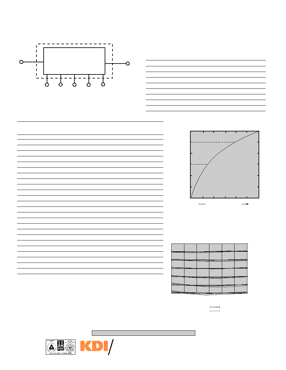
Current (GT Models): +10 mA, maximum attenuation. 0 mA,
zero attenuation for all current controlled
models.
Power Requirements: ±15 volts at ±50 mA maximum. For all
models. 1GT, 2GT, GA (except GT)
Control Voltage (1 GT and 0≠10 volts produces 0≠32 dB for 32 dB
2 GT Models): models and 0≠64 dB for 64 dB models.
Other values of control voltage can be
provided on request.
Maximum Control Voltage: 10 VDC
0 5 10
60
50
40
30
20
10
A
T
T
E
N
U
A
T
I
O
N
(dB)
BIAS CURRENT (mA)
Typical curve of attenuation vs. bias current for GT Models.
Control Input Impedance: 10 K ohms, 20 pf.
Switching Period: Standard models can be changed from any
value of attenuation to any other value in 10
microsec. Units can be provided with switch-
ing speed to 300 nanosec. on request. Speed
is related to maximum attenuation required.
That is, 32 dB models are faster than 64 dB
models. Insertion Loss will increase by a fac-
tor of 1.6 on higher speed models.
Connectors: SMA standard, others on request.
BASIC MODEL TYPES
KEY: Inches[Millimeters] .XX ±.03 .XXX ±.010 [.X ±0.8 .XX ±0.25]
11-5-02
60 South Jefferson Road, Whippany, NJ 07981
Tel: 973-887-8100 ∑ Fax: 973-884-0445
email: sales@mcekdi-integrated.com
See us on the web @ www.mcekdi-integrated.com
An MCE Company
TRIANGLE
C O R P O R A T I O N
KEY: Inches[Millimeters] .XX ±.03 .XXX ±.010 [.X ±0.8 .XX ±0.25]
60 South Jefferson Road, Whippany, NJ 07981
Tel: 973-887-8100 ∑ Fax: 973-884-0445
E-Mail: kdisales@aol.com
See us on the web @ www.kditriangle.com
10/98
ATTENUATORS, PIN DIODE SERIES GT, 1GT,
0.25≠18 GHz
2GT, GA
**Select type by adding to Model No.
(1) Subtract 0.5 dB from insertion loss for GT and 1 GT Series
Frequency
Max
Max (1)
Atten
GT-( )
1, 2 GT-( )
GA
Type**
GHz
VSWR
IL dB
Range dB
Models
Models
Models
(10)
0.25≠0.5
.
1.5
5
2.3
5
32
1
11
21
(11)
0.25≠0.5
.
1.5
5
2.3
5
64
1
11
21
(13)
0.5≠1.0
1.5
5
2.5
5
32
2
12
22
(16)
0.5≠2.0
1.75
2.8
5
32
3
13
23
(17)
0.5≠2.0
1.75
2.8
5
64
3
13
23
(19)
1.0≠2.0
1.5
5
2.8
5
32
4
14
24
(20)
1.0≠2.0
1.5
5
2.8
5
64
4
14
24
(22)
1.0≠4.0
1.75
3.1
5
32
5
15
25
(23)
1.0≠4.0
1.75
3.1
5
64
5
15
25
(25)
2.0≠4.0
1.5
5
3.1
5
32
4
14
24
(26)
2.0≠4.0
1.5
5
3.1
5
64
4
14
24
(28)
2.0≠8.0
1.8
5
3.7
5
32
6
16
26
(29)
2.0≠8.0
1.8
5
3.7
5
64
6
16
26
(30)
4.0≠8.0
1.75
3.4
5
32
6
16
26
(31)
4.0≠8.0
1.75
3.4
5
64
6
16
26
(32)
4.0≠12.0
1.9
5
4.0
5
32
7
17
(38)
6.0≠18.0
2.2
5
4.2
5
64
7
17
(39)
8.0≠12.4
2
5
3.8
5
32
7
17
26
(40)
8.0≠12.4
2.1
5
3.3
5
64
7
17
(41)
8.0≠18.0
2.2
5
3.75
32
7
17
(43)
12.0≠18.0
2
3.75
32
7
17
26
(50)
2.0≠18.0
2.2
5
5.0
5
32
8
18
26
(51)
2.0≠18.0
2.5
5
5.0
5
64
8
18
26
MODEL TYPE SPECIFICATIONS
"GA" MODELS-DIGITAL LOGIC:
TTL COMPATIBLE.
NO. OF BITS = 8 L.S.B. = .25 dB ATTENUATION: 63.75 dB
BIT SIZE
.25
.5
1
2
4
8
16
32
LOGIC
0
0
0
0
0
0
0
0
= REF. (INS. LOSS)
LOGIC
0
0
0
1
0
1
0
0
= 10 dB
LOGIC
0
0
0
0
1
0
1
0
= 20 dB
LOGIC
0
0
0
1
1
1
1
0
= 30 dB
LOGIC
0
0
0
0
0
1
0
1
= 40 dB
LOGIC
0
0
0
1
0
0
1
1
= 50 dB
LOGIC
0
0
0
0
1
1
1
1
= 60 dB
LOGIC
1
1
1
1
1
1
1
1
= 63.75 dB
NOTE: Least Sig. Bit for 32 dB unit is .125 dB. Most Sig. Bit is 16 dB.
ATTENUATOR,
LINEARIZER
and D/A CONVERTER
RF
RF
∑ ∑ ∑ ∑
LOGIC INPUTS
"GA" MODELS
0 4 8
60
50
40
30
20
10
A
T
T
E
N
U
A
T
I
O
N
(dB)
CONTROL VOLTAGE (V)
VOLTAGE VS ATTENUATOR
MODEL 1GT.
00001111
00010011
00000101
00001010
00011110
00010100
00000000
0
10
20
30
40
50
60
A
T
T
E
N
U
A
T
I
O
N
(
d
B
)
D
I
G
I
T
A
L
W
O
R
D
0.5
2.0
.75
3.0
1.0
4.0
1.25
5.0
1.5
6.0
1.75
6.0
2
8.0
NOTE: SINGLE OCTIVE MODELS
ARE FLATTER
LEGEND _____ +85∞C
+25∞C
-54∞C
TEMPERATURE COMPENSATED
DIGITALLY CONTROLLED ANALOG
PIN DIODE ATTENUATORS SERIES GA-TT/TR
Outline
Outline
Outline
26
26
26
26
(14)
0.5≠1.0
1.5
5
2.5
5
64
2
12
22
Typical Curves for GA-17-T or GA-29-T
10/98
An MCE Company
TRIANGLE
C O R P O R A T I O N
KEY: Inches[Millimeters] .XX ±.03 .XXX ±.010 [.X ±0.8 .XX ±0.25]
60 South Jefferson Road, Whippany, NJ 07981
Tel: 973-887-8100 ∑ Fax: 973-884-0445
E-Mail: kdisales@aol.com
See us on the web @ www.kditriangle.com
ATTENUATORS, PIN DIODE SERIES GT, 1GT,
0.25≠18 GHz
2GT, GA
CHART A
ATTENUATION ACCURACY VS FREQUENCY
@ 25∞C Temperature
SERIES GA, GT, 1GT 2GT
± 0.5 dB to 10 dB
± 0.75 dB to 10 dB
± 1.0 dB to 20 dB
± 1.25 dB to 20 dB
± 1.5 dB to 30 dB
± 1.75 dB to 30 dB
± 1.7 dB to 40 dB
± 2.0 dB to 40 dB
± 2.5 dB to 64 dB
± 3.5 dB to 64 dB
[See note (4)]
Octave Models (2:1 Frequency)
Greater than Octave Models
CHART B
ATTENUATION ACCURACY VS FREQUENCY
AND TEMPERATURE
over the +10∞C to +40∞C temperature range
SERIES GA, GT, 1GT, 2GT
CHART D
ATTENUATION ACCURACY VS FREQUENCY
AND TEMPERATURE
over the 0∞C to +70∞C temperature range
SERIES GA-(TR) 1,2-GT-(TR)
[See note (4)]
[See note (4)]
Attentuation accuracy given above assumes 0.1% regulation of power supply voltages
*Add T or R suffix (see temperature information).
Notes:
1. Harmonic Distortion: Approximately ≠50 dBc for Pin
0 dBm at a frequency
of 1.0 GHz for most units. This value improves by approximately 10 dB per
octave as the frequency increases; however, since this value is dependent
on bandwidth of the unit, power input, and switching speed required, the
factory should be consulted if harmonic content is an important system
requirement.
2. Two/Tone Intermodulation Products: Second and third order products
approximately 50 dBC for Pin
0 dBm (each signal) at all attenuation
settings.
3. If a narrow frequency bandwidth is required, KDI/Triangle can supply a unit
that is electrically optimized for that bandwidth. Mechanical dimensions will
remain the same as the standard unit, and the price will generally be lower.
Specify the frequency range when ordering a narrow bandwidth model, and
a special part number will be assigned.
4. Add 1.5 dB to all accuracy numbers for types (50) and (51). Two RF
connectors are in line.
5. Attenuation vs. temperature only is ± 0.02 dB/∞C typical. (At 64 dB)
6. When ordering, add suffix indicating required temperature compensation
range to the model number, i.e. the 1-GT-32-T, compensated over the tem-
perature range ≠55∞C to +85∞C, would be ordered as 1-GT-32-TT. If com-
pensation from 0∞C to +70∞C is required, the model number would be 1-GT-
32-TR. (See "attenuation accuracy vs frequency and temperature" tables for
specifications.)
7. Monotonicity guaranteed for all models.
Octave Models (2:1 Frequency) Greater than Octave Models
±0.4 dB to 10 dB ±0.5 dB to 10 dB
±0.75 dB to 20 dB ±1.0 dB to 20 dB
±1.0 dB to 30 dB ±1.5 dB to 30 dB
±1.25 dB to 40 dB ±1.75 dB to 40 dB
±1.75 dB to 64 dB ±3.0 dB to 64 dB
CHART C
ATTENUATION ACCURACY VS FREQUENCY
AND TEMPERATURE
over the ≠55∞C to +85∞C temperature range
SERIES GA-(TT), 1, 2GT(TT)
[See note (4)]
Attentuation accuracy given above assumes 0.1% regulation of power
supply voltages
Octave Models (2:1 Frequency) Greater than Octave Models
±0.75 dB to 10 dB ±1.0 dB to 10 dB
±1.2 dB to 20 dB ±1.5 dB to 20 dB
±1.5 dB to 30 dB ±2.0 dB to 30 dB
±2.0 dB to 40 dB ±2.5 dB to 40 dB
±3.0 dB to 64 dB ±4.0 dB to 64 dB
Octave Models (2:1 Frequency) Greater than Octave Models
±0.6 dB to 10 dB ±0.8 dB to 10 dB
±1.0 dB to 20 dB ±1.5 dB to 20 dB
±1.3 dB to 30 dB ±1.7 dB to 30 dB
±1.7 dB to 40 dB ±2.2 dB to 40 dB
±2.4 dB to 64 dB ±3.5 dB to 64 dB
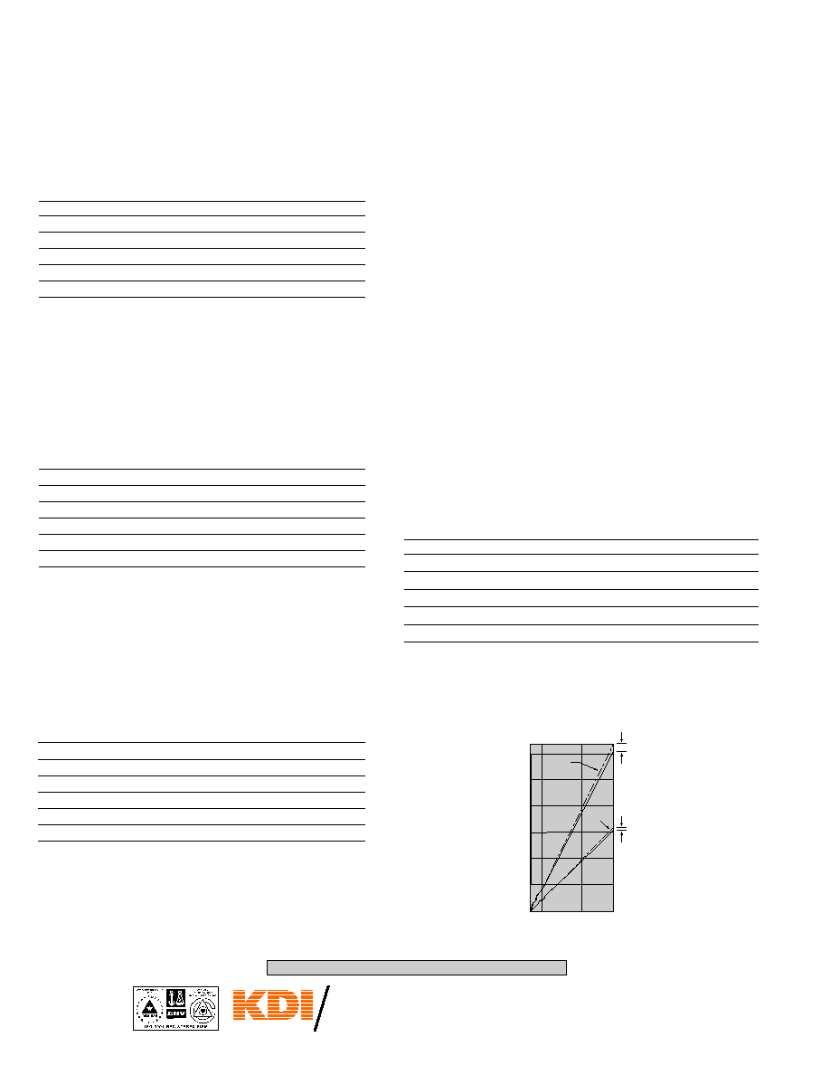
CONTROL VOLTAGE
(V)
A
T
T
E
N
U
A
T
I
O
N
(
d
B
)
TYPICAL CURVE OF ATTENUATION
VS. CONTROL VOLTAGE FOR 2GT MODELS
0 1 5 8
0
10
20
30
40
50
60
64
BEST FIT
STRAIGHT LINE
BEST FIT
STRAIGHT
LINE
1
.
0
d
B
0
.
5
d
B

An MCE Company
TRIANGLE
C O R P O R A T I O N
KEY: Inches[Millimeters] .XX ±.03 .XXX ±.010 [.X ±0.8 .XX ±0.25]
60 South Jefferson Road, Whippany, NJ 07981
Tel: 973-887-8100 ∑ Fax: 973-884-0445
E-Mail: kdisales@aol.com
See us on the web @ www.kditriangle.com
10/98
ATTENUATORS, PIN DIODE SERIES GT, 1GT,
0.25≠18 GHz
2GT, GA
SERIES 1GT, 2GT (VOLTAGE INPUT)
MECHANICAL OUTLINES
SERIES GT (CURRENT INPUT)
MECHANICAL OUTLINES
Out-
A
B
C
D
E
F
G
line
in[mm]
in[mm]
in[mm]
in[mm]
in[mm]
in[mm]
in[mm]
1
5.00[127,0] 3.00[76,2] 4.600[116,84] 2.800[71,12]
.38[9,65]
0.75[19,1] 0.19[0,48]
2
5.00[127,0] 2.50[63,5] 4.600[116,84] 2.300[58,42]
.38[9,65]
0.30[7,6]
0.19[0,48]
3
3.50[88,9]
3.50[88,9]
3.100[78,74]
3.300[83,82]
.44[11,18]
0.30[7,6]
0.25[6,4]
4
3.50[88,9]
1.75[44,45] 3.100[78,74]
1.550[39,37]
.38[9,65]
0.38[9,65] 0.19[0,48]
5
2.50[63,5]
2.50[63,5]
2.100[53,3]
2.300[58,42]
.44[11,18]
0.30[7,6]
0.25[6,4]
6
1.80[45,7]
1.80[45,7]
1.400[35,56]
1.600[40,64]
.44[11,18]
0.35[8,9]
0.25[6,4]
7
1.50[38,1]
1.50[38,1]
1.100[27,94]
1.300[33,02]
.44[11,18]
0.35[8,9]
0.25[6,4]
8
2.00[50,8]
1.81[45,97]
1.800[45,7]
1.050[26,67]
.44[11,18]
0.25[6,4]
0.24[6,10]
SERIES GA (DIGITAL INPUT)
MECHANICAL OUTLINES
C
A
SMA
FEMALE
TYP.
B
D
A-C
0.38
[9,7]
TYP.
E TYP.
0.125[3,18] DIA THRU
4 MTG. HOLES
0.10
[2,5]
1.00[25,4]
GND
-15V
+15V
C.V.
R
F
TYPES
50 & 51
(See Note 4)
2
F
C
A
SMA FEMALE
TYP.
B D
A-C
0.38
[9,7]
TYP.
0.093[2,36] DIA. THRU
4 MTG. HOLES
0.10
[2,5]
GND
RF
GT-50,GT-51
(See Note 4)
2
BIAS
G
E
RF
F TYP.
C
A
SMA
FEMALE
TYP.
B
D
0.38
[9,7]
TYP.
P
O
W
E
R
/
L
O
G
I
C
E
0.20
[5,1]
0.125[3,18] DIA. THRU
4 MTG. HOLES
1.00
[2,5]
PIN 9
PIN 1
ITT CANNON
DA-15P OR EQUIV.
F
H
RF
G
Out-
A
B
C
D
E
F
line
in[mm]
in[mm]
in[mm]
in[mm]
in[mm]
in[mm]
11 5.00[127,0]
3.00[76,2] 4.600[116,84] 2.800[71,12]
0.75[19,1] 0.19[0,48]
12 5.00[127,0]
2.50[63,5] 4.600[116,84] 2.300[58,42]
0.32[8,12] 0.19[0,48]
13
3.50[88,9]
3.50[88,9]
3.100[78,74]
3.300[83,82]
0.63[16,0]
0.25[6,4]
14
3.50[88,9]
1.75[44,45] 3.100[78,74]
1.550[39,37]
0.38[9,65] 0.19[0,48]
15
2.50[63,5]
2.50[63,5]
2.100[53,3]
2.300[58,42]
0.32[8,12]
0.25[6,4]
16
1.80[45,7]
1.80[45,7]
1.400[35,56]
1.600[40,64]
0.35[8,9]
0.25[6,4]
17
1.50[38,1]
1.50[38,1]
1.100[27,94]
1.300[33,02]
0.35[8,9]
0.25[6,4]
18
2.00[50,8]
1.81[45,97]
1.800[45,7]
1.050[26,67]
0.25[6,4]
0.24[6,1]
Out-
A
B
C
E
F
G
H
line
in[mm]
in[mm]
in[mm]
in[mm]
in[mm]
in[mm]
in[mm]
21 5.00[127,0] 3.00[76,2] 4.600[116,84]
0.75[19,1]
0.13[3,30]
0.75[19,1]
0.19[4,83]
22 5.00[127,0] 2.50[63,5] 4.600[116,84]
0.32[8,12]
0.13[3,30]
0.32[8,12]
0.19[4,83]
23 3.00[76,2] 3.50[88,9] 3.100[78,74]
0.38[9,65]
0.13[3,30]
0.35[8,9]
0.25[6,4]
24 3.50[88,9] 1.75[44,45] 3.100[78,74]
0.40[10,2]
0.10[2,5]
0.35[8,9]
0.19[4,83]
25 2.50[63,5] 2.50[63,5]
2.100[53,3]
0.32[8,12]
0.13[3,30]
0.32[8,12]
0.25[6,4]
26 2.50[63,5] 2.50[63,5]
2.100[53,3]
0.50[12,7]
0.13[3,30]
0.50[12,7]
0.25[6,4]
D
in[mm]
2.750[69,85]
2.250[57,15]
2.750[69,85]
1.550[39,37]
2.250[57,15]
1.750[44,45]